
broken charger connection alarm circuit
The circuit operates by monitoring the connection status of the load. It typically includes a voltage divider, a comparator, and an indicator, such as an LED, to signal the connection status. The voltage divider reduces the input voltage to a level suitable for the comparator, which compares the divided voltage against a reference voltage. If the load is properly connected, the voltage at the comparator's input will exceed the reference voltage, resulting in a high output signal. This signal can then be used to illuminate an LED, indicating that the load is connected correctly.
In cases where the load is disconnected or improperly connected, the voltage at the comparator will fall below the reference level, leading to a low output signal. This condition can also be used to turn off the LED, providing a clear visual indication of the issue. The circuit's design ensures that it can operate safely across a variety of battery types and low-voltage devices while maintaining a maximum current of 1A, making it versatile for different applications in battery management systems.
Overall, this circuit serves as a crucial safety feature in battery charging systems, preventing potential damage to the charger or load due to improper connections. Its ability to operate across a wide voltage range enhances its applicability in various electronic devices and systems, ensuring reliable performance and user feedback.This circuit can be useful to detect if the load of any battery charger or plug-in adapter supply is not properly connected. The load can be a set of batteries to be charged or any other type of battery or low dc voltage operated device.
The circuit can safely operate over a 3 to 15V range and 1A max. Current, provided the supply voltage is about one volt higher than the voltage required by the load.. 🔗 External reference
Related Circuits

The circuit depicted involves transistors VT1, VT2, and resistor R1, which form a constant current source for charging capacitor C2 in a linear manner. Transistors VT3, VT4, and resistor R2 create a constant current source for discharging capacitor C2,...
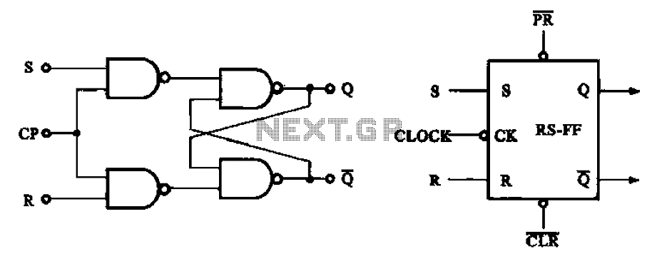
The asynchronous RS flip-flop mentioned earlier is not synchronized with the system clock signal. In contrast, the synchronous RS flip-flop incorporates synchronization, allowing it to operate in conjunction with the clock signal. Figure (a) illustrates the circuit configuration of...
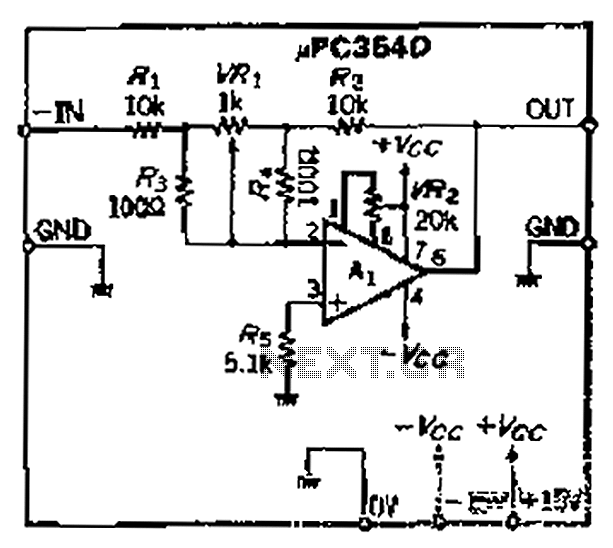
The loop gain of the operational amplifier (OP) is primarily influenced by the ratio of the input resistor to the feedback resistor. Consequently, any resistance error can lead to a corresponding gain error, which necessitates the use of high-precision...
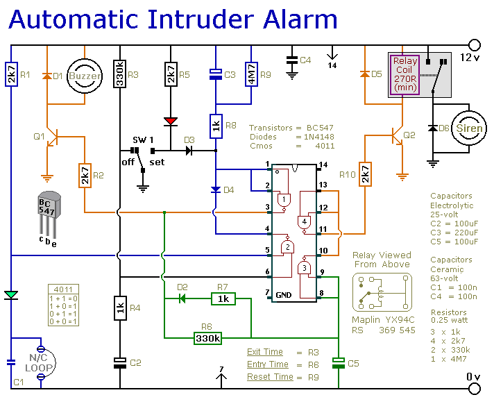
This is a simple single-zone burglar alarm circuit. Its features include automatic Exit and Entry delays and a timed Bell/Siren Cut-Off. It's easy to use. First check that the building is secure and that the green LED is lit....

Q1 and Q2 form a constant current drive defined by R2. The current (I) approximates the reciprocal of R2 in the circuit shown for values of I greater than 1 amp. The pulse current is drawn from C1, which...

The MAX712 charger requires a power supply with an output voltage that is at least 1.5V higher than the maximum battery voltage. Charge completion is determined by a voltage-slope detecting analog-to-digital converter, a timer, and a temperature window comparator. The...
Warning: include(partials/cookie-banner.php): Failed to open stream: Permission denied in /var/www/html/nextgr/view-circuit.php on line 713
Warning: include(): Failed opening 'partials/cookie-banner.php' for inclusion (include_path='.:/usr/share/php') in /var/www/html/nextgr/view-circuit.php on line 713