
The oscillator and trigger circuit with operational amplifier
The multivibrator circuit, as shown in Figure a, typically consists of two active devices, such as transistors or operational amplifiers, configured to oscillate between two states. This circuit can generate a square wave output by charging and discharging a capacitor through resistors, producing a repetitive waveform that is characterized by its distinct high and low voltage levels. The frequency of the output waveform can be adjusted by varying the values of the resistors and capacitors in the circuit.
In Figure b, the flip-flop circuit serves as a bistable multivibrator. It changes its output state based on the input signal's falling edge. This characteristic makes it useful for applications requiring synchronization or data storage. The flip-flop can be implemented using various logic gates, such as NAND or NOR gates, and it often includes feedback paths to maintain its state until a new input signal is received.
Figure c illustrates the monostable circuit, which is designed to produce a single output pulse in response to a trigger input. The duration of the output pulse can be controlled by the timing components, typically a resistor and a capacitor. This circuit is commonly used in applications such as pulse width modulation or signal conditioning, where a clean, defined pulse is necessary for further processing.
Lastly, Figure d presents the Schmitt trigger circuit, which is utilized for waveform shaping by providing hysteresis in the input signal. This circuit transforms a noisy or slowly varying input signal into a clean digital output. The Schmitt trigger's threshold levels are defined by the feedback mechanism, allowing it to provide a stable output even in the presence of noise. This characteristic makes it suitable for applications in digital signal processing, where signal integrity is paramount.Fig a shows a multivibrator circuit which can generate square wave signal; Figure b is a flip-flop circuit which uses the under edge of the input signal to generate a trigger pulse signal. Figure c is a monostable circuit which can be used for waveform shaping or other signal conversion circuits.
Figure d shows a Schmitt trigger circuit for waveform shaping.. 🔗 External reference
Related Circuits
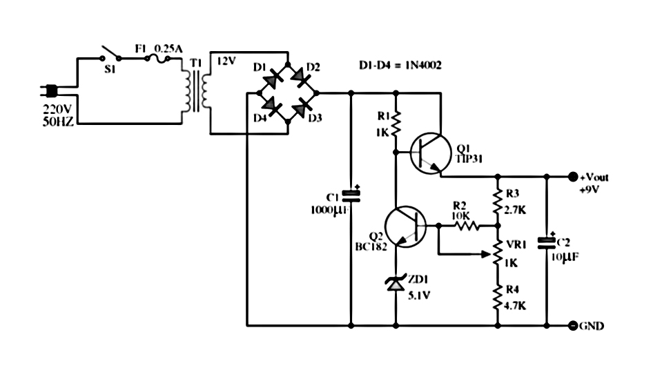
The power supply described utilizes a regulator composed of two NPN transistors. One transistor functions as the power regulator, while the other controls the output voltage. This power supply offers an adjustable output voltage range of 6-12 VDC. The...
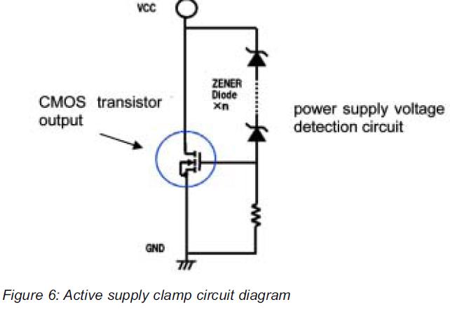
This article presents a high reliability 1200V High Voltage Integrated Circuit (1200V HVIC) for half bridge driver applications, aimed at reducing the IC's supply current by approximately 50%. The 1200V High Voltage Integrated Circuit (HVIC) is designed specifically for half-bridge...
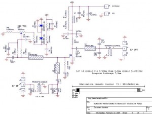
This FM 88-108 MHz radio amplifier is equipped with a BLF 245 and can be used with a heatsink from a processor and a cooler. The BLF 245 datasheet can be downloaded. The FM 88-108 MHz radio amplifier utilizing the...
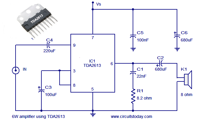
A simple and easy-to-build Hi-Fi audio power amplifier circuit is presented here. This 6-watt Hi-Fi audio amplifier circuit utilizes the TDA2613 integrated circuit (IC). The circuit design employs the TDA2613, which is a high-performance audio amplifier IC known for its efficiency...
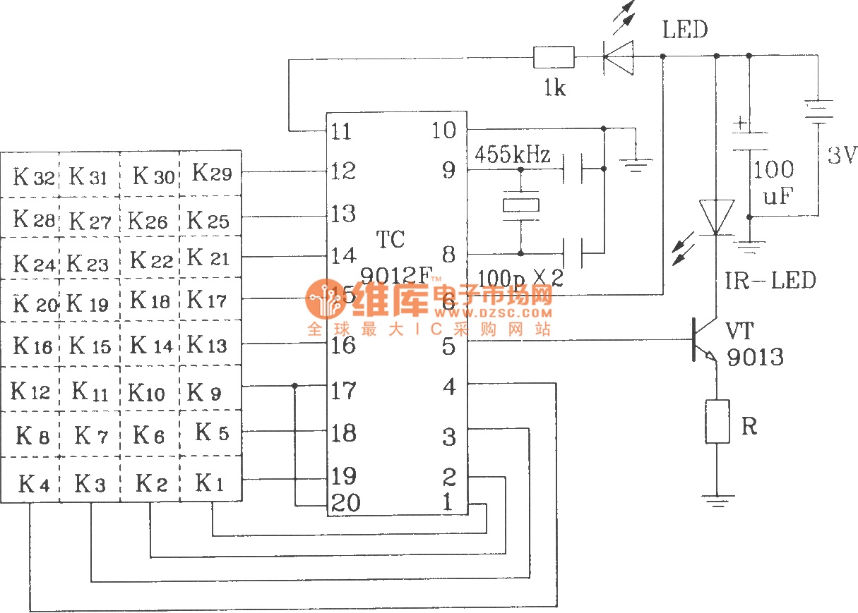
The TC9012 is a specialized off-screen remote control code transmitter. It incorporates an oscillator, divider timing generator, system code latch, data storage, key scan input, key scan output, and carrier control and output units. The internal 8-bit system code...
One of the most interesting projects to work with is that of a synthesizer that can accurately generate desired frequencies. This synthesizer uses just three CMOS chips and one PNP transistor. It is a fact that the transistor may...