
Relay control auto transformer one AC power supply circuit

This circuit utilizes a transformer with a primary-to-secondary winding ratio of 24:220, which translates to a transformation ratio (k) of approximately 0.11. The primary function of the circuit is to regulate the output voltage based on the input voltage levels.
When the input voltage falls below the threshold of 170V, relay KAi engages. This relay is connected to an adjustment potentiometer, RPi, which allows for fine-tuning of the output voltage to a stable 187V. The calculation is based on the formula: output voltage = input voltage (1 + k) - 170(1 + 0.11), confirming the output at this lower threshold.
In situations where the input voltage exceeds 260V, relay KA2 is activated. This relay is linked to another potentiometer, RP2, enabling the adjustment of the output voltage to a maximum of 231V. The output voltage is derived from the input voltage using the formula: output voltage = 260(1 - k) = 231V, ensuring that the output remains within safe operational limits.
During normal operation, when the input voltage fluctuates between 170V and 260V, both relays KAi and KA2 are released. In this state, the output voltage mirrors the input voltage, ensuring a direct pass-through without any transformation. This design ensures that the system can handle a wide range of input voltages while providing stable output voltages under varying conditions.
Overall, this circuit is critical for applications requiring voltage regulation and protection against overvoltage and undervoltage conditions, making it suitable for various electronic devices and systems.When the input voltage is 170-260V AC range, the output AC voltage 187-231V range. Transformer ratio is k = 24/220 = 0.11. When the input voltage drops below 170V, the relay KAi pull (RPi adjustment potentiometer setting), the output voltage is 170 (l + k) -170 (1 + 0 11.) = 187 (V); when the input Tun when the pressure is greater than 260V, KA2 pull (adjusted RP2 setting), the output voltage is 260 (lk) - 260 (1-0 11.) a 231 (V); when the input voltage at 170 ~ 260V between when, KAi, KA2 were released, the output voltage equal to the input voltage.
Related Circuits

This is a design schematic for sensing the electromagnetic field. The circuit is built using a 741 operational amplifier (op-amp) IC. It can detect electromagnetic fields, including those from hidden wiring. A 1mH inductor is employed for sensing the...
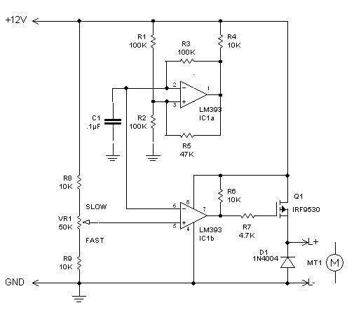
The inquiry pertains to identifying the component within the circuit that regulates the minimum RPM achievable. The current operational range of the motor is between 1400 and 3700 RPM, and there is an interest in modifying the circuit to...
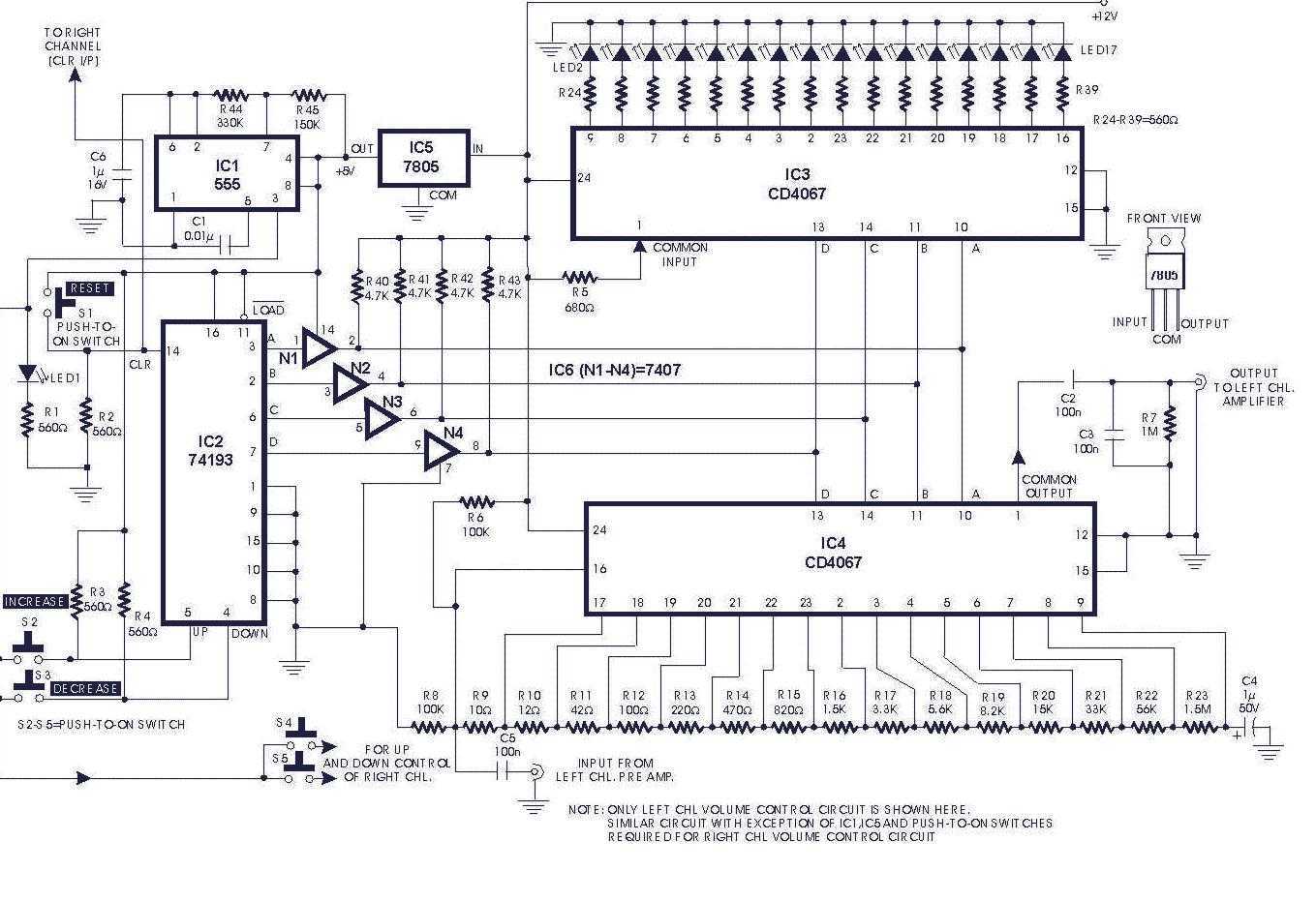
Circuit of a digital volume control using six discrete ICs, including a 5V regulator, is presented. IC1 (555) is configured to function as astable flip-flop. Its frequency or period may be adjusted by proper choice of resistors R44, R45...
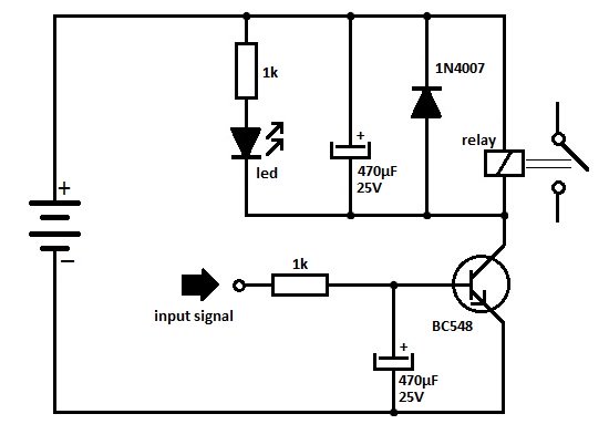
One of the serious problems in relay-operated circuits is the relay clicking or chattering during the on/off operation of the relay driver transistor. This issue can lead to unreliable circuit performance and may cause premature wear of the relay...
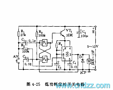
555 low power timing circuit diagram. The diagram is from the technical information of Chinaicmart. For more detailed information about the circuit diagram. The 555 timer IC is widely utilized in various applications due to its versatility and ease of...

CO2 gas shielded arc welding power supply electromagnetic vibration circuit is commonly used in farm machinery repair. The maximum arc voltage is 30V, with a maximum welding current of 300A. The wire feed speed ranges from 0 to 12...