
echo effect circuit
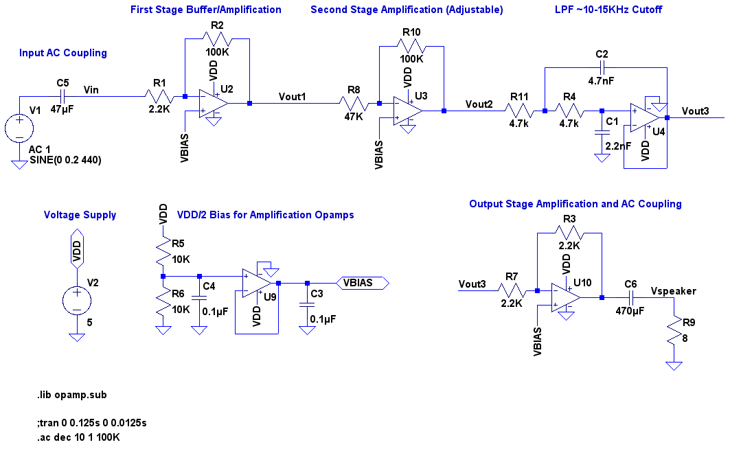
The audio echo effect circuit is designed to provide a versatile platform for audio processing applications. The core components include an electret microphone for sound input, an mbed microcontroller for processing, and an LM358 operational amplifier for signal amplification. The AC coupling of the microphone input ensures that any DC offset is removed, allowing the audio signal to be centered around zero volts. The first amplification stage boosts the microphone signal, which is then passed through an adjustable gain stage, allowing for tailored echo effects.
The low-pass filter (LPF) is critical for eliminating unwanted high-frequency noise, ensuring that only the desired audio frequencies are processed. The cutoff frequency, set between 10 kHz and 15 kHz, is chosen to balance clarity and echo effect. The use of an mbed microcontroller allows for rapid development and flexibility in coding, utilizing an Analog-to-Digital Converter (ADC) to capture the input audio signal and a Digital-to-Analog Converter (DAC) to output the processed audio.
The echo effect is created by storing samples of the incoming audio signal in a buffer, with the delay time adjustable via a potentiometer. The processing algorithm calculates the output signal by mixing the current input with a delayed version of itself, effectively creating the echo. The parameters for maximum and minimum delay and gain are defined in the code, allowing for real-time adjustments during operation.
The circuit can be easily modified for different audio sources, including electric guitars and microphones, by adjusting component values such as resistors and capacitors. The design emphasizes cost-effectiveness, with the potential to build the entire system for under $15, making it accessible for hobbyists and audio enthusiasts.
In summary, this audio echo effect circuit not only serves as a practical application for creating delay effects but also stands as a platform for further experimentation and customization in audio processing. The combination of straightforward circuitry and programmable microcontroller capabilities allows for a wide range of creative audio effects.A video of my friend James playing his electric guitar, patched through the audio echo effect system, and then to his amp. I didnG ‚¬ t make any effort to prove that this isnG ‚¬ t a conspiracy, so youG ‚¬ ll have to take my word that the echo effect is actually happening on the breadboard and not some hidden pedal or options on h
is amp. While IG ‚¬ m at it, I apologize for the camera phone video quality. This project is an audio echo/delay effect G ‚¬ pedalG ‚¬ ½ of a sort, though I did most of the testing with a regular electret microphone and ear buds or external speakers. The circuitry of the G ‚¬ pedalG ‚¬ ½ is fairly straight forward: the microphone/input is AC coupled, then amplified around a VDD/2 bias (IG ‚¬ m running on a single supply) across two stages, one of which is adjustable, then passed through a low pass filter at around 10-15KHz to clean out any high frequency in the input, and fed to a microcontroller for some processing.
I used an mbed, which is a LPC1768 hardware platform plus all of that arduino pseudo-coding, because theyG ‚¬ re pretty neat and super quick to develop with, but any micro with an ADC and DAC will do. The output of the microcontrollerG ‚¬ s DAC is smoothed (LPF) out by a cap and fed to a final amplification stage, and then AC coupled to a speaker/output.
Although IG ‚¬ ve labeled this particular project Audio Echo Effect, you can really do whatever youG ‚¬ d like on the mbed/micro for the processing, so I like to think about it as more of a general audio effect platform I can tinker with (though a DSP instead of a micro would probably do better). The mbed and LM358s are the only ICs, the rest of the parts are passives and connectors. Substituting the mbed for a more economical microcontroller with an ADC, DAC (or even building an R2R DAC), and sufficient memory, this project can be built for under $15.
There is a voltage divider potentiometer connected to an ADC of the mbed to adjust the amount of echo/delay. The actual delay effect is implemented by the following DT system: The negative DELAY power of z corresponds to the G ‚¬ delayG ‚¬ ½ variable and the G multiplier corresponds to the G ‚¬ inv_gainG ‚¬ ½ variable in the mbed code.
Although the mbed code does support adjusting the gain variable with a voltage divider potentiometer hooked up to p16, I found that the echo effect worked quite well with the gain fixed at 1/3. Below is the EAGLE schematic, LTspice schematic (for some frequency response simulation of the surrounding analog parts), mbed code, and pictures/video.
With the main low pass filter at around 11kHz cutoff, the sampling frequency should be around 22kHz. Since IG ‚¬ m essentially sampling as fast as possible in the mbed code, itG ‚¬ s not clear what the exact sampling frequency is, but itG ‚¬ s likely to be excessively high. Sampling explicitly at 22kHz should allow for a better use of sample memory as well as a longer echo effect.
Changing R4 to 10K helps for microphone applications, but input from a electric guitar pickup comes in pretty strong so I found 47K worked well when using an electric guitar. #include "mbed. h" #define MAX_DELAY 15000 #define MIN_DELAY 50 #define MAX_GAIN 25 #define MIN_GAIN 2 /* ADC for the microphone/input, DAC for the speaker/output */ AnalogIn mic(p19); AnalogOut speaker(p18); /* Two potentiometer voltage dividers for the delay/gain control knobs */ AnalogIn delay_knob(p15); AnalogIn gain_knob(p16); unsigned short buffer[MAX_DELAY]; /* inv_gain = 1 / gain; it`s faster to avoid floating point during the main loop */ int inv_gain = 3; int delay = MAX_DELAY; void read_knobs(void) { delay = delay_knob*MAX_DELAY; //gain = gain_knob*MAX_GAIN; if (delay < MIN_DELAY) delay = MIN_DELAY; /*if (gain < MIN_GAIN) gain = MIN_GAIN; if (gain = MAX_GAIN) gain -= 1;*/ } int main() { int i; /* Fill up the sample buffer first */ for (i = 0; i < delay; i+) buffer[i] += mic.
read_u16(); fo 🔗 External reference
Related Circuits
Infrared heat is emitted by an object during non-contact temperature measurement. The measured signal is weak, necessitating the use of highly sensitive thermal infrared sensors with minimal noise. Consequently, the amplifier circuit must also meet stringent requirements, as standard...
An LED flasher circuit can be constructed using a 555 integrated circuit (IC). The use of the 555 IC allows for greater flexibility in adjusting the flashing rate of the LED. This LED flasher circuit is similar to other...
This page describes a battery tester designed to characterize batteries and save the results on a microSD card. The battery tester circuit is engineered to evaluate the performance and capacity of various battery types, providing accurate and reliable data storage...
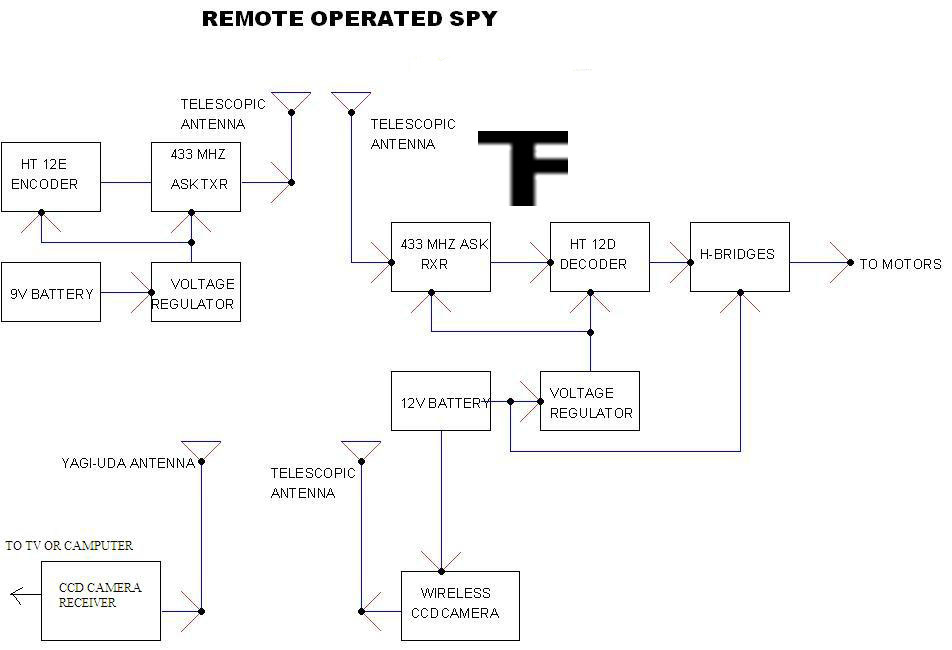
A robot that operates when you send messages through your phone. Your mobile device serves as the remote controller for the robot. This means that if the robot is in London and you are in Mumbai, you can still...
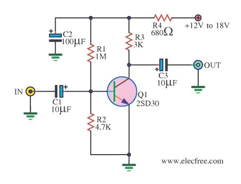
When there is a need to amplify audio signals from various sources before they reach a custom amplifier, a preamplifier (or preamp) is typically employed. This document suggests a specific circuit that is interesting due to its use of...
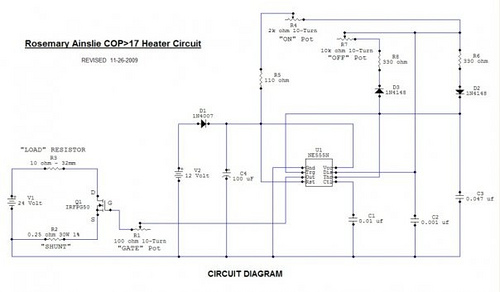
Recently, the Overunity and Energetics online forums, which serve as significant platforms for members of the Open Source and Free Energy communities, have been discussing a remarkable phenomenon known as the Rosemary Ainslie Circuit. This circuit is named after...
Warning: include(partials/cookie-banner.php): Failed to open stream: Permission denied in /var/www/html/nextgr/view-circuit.php on line 713
Warning: include(): Failed opening 'partials/cookie-banner.php' for inclusion (include_path='.:/usr/share/php') in /var/www/html/nextgr/view-circuit.php on line 713