
Led Flasher Circuit Using 555 IC
The LED flasher circuit utilizing the 555 timer IC operates in astable mode, which allows it to continuously toggle the output state between high and low, thereby creating a flashing effect for the connected LED. The circuit typically consists of the 555 timer, resistors, capacitors, and the LED itself.
In this configuration, the frequency of the flashing can be adjusted by changing the values of the resistors (R1 and R2) and the capacitor (C1) connected to the 555 timer. The relationship governing the frequency (f) of the output signal can be expressed by the formula:
\[ f = \frac{1.44}{(R1 + 2R2) \cdot C1} \]
Where:
- R1 is the resistance connected between the discharge pin (Pin 7) and Vcc.
- R2 is the resistance connected between the discharge pin (Pin 7) and the threshold pin (Pin 6).
- C1 is the timing capacitor connected between the threshold pin (Pin 6) and ground.
The duty cycle, which determines the proportion of time the LED is on compared to off, can also be influenced by the resistor values. The duty cycle can be calculated using the formula:
\[ Duty Cycle = \frac{R2}{R1 + 2R2} \times 100\% \]
This allows designers to create various flashing patterns by selecting appropriate component values, making the circuit versatile for different applications such as visual alerts, decorative lighting, or signaling devices.
Power supply requirements for the circuit are typically modest, with the 555 timer functioning effectively within a voltage range of 4.5V to 15V. The LED should be connected in series with a current-limiting resistor to prevent damage due to excessive current. The choice of the resistor value will depend on the LED specifications and the supply voltage.
Overall, the 555 timer-based LED flasher circuit is a straightforward yet effective solution for generating flashing light effects, suitable for a variety of electronic projects.LED flasher circuit can be built based on 555 IC. Using 555 IC, the flashing rate can be more flexible to adjust. This LED flasher circuit is similar to our.. 🔗 External reference
Related Circuits
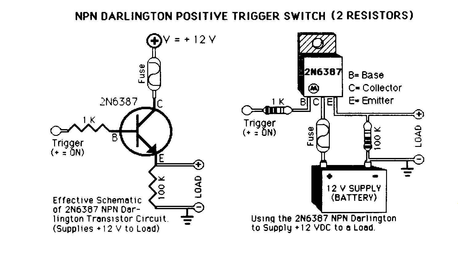
Mechanical 12 Volt DC automotive relays are commonly used in the car audio industry to activate amplifiers, lock doors, and roll up windows. However, solid-state switches provide an alternative method for activating these loads. The reliance on mechanical relays,...
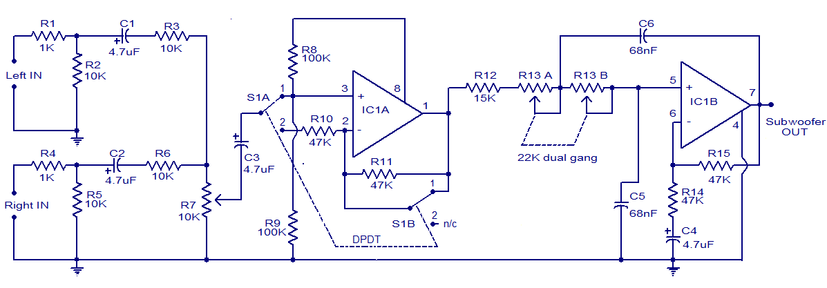
The circuit diagram depicts a simple subwoofer filter that operates on a 12V DC supply, making it particularly useful for automobile subwoofer applications. This circuit functions as a low-pass filter, with an adjustable pass frequency ranging from 60 to...
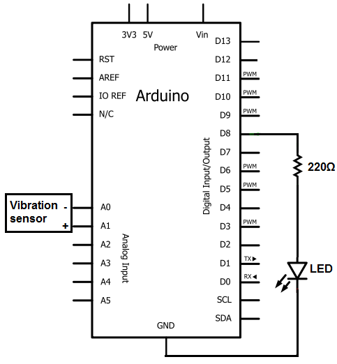
The sensors consist of a thin strip of piezoelectric material with a rivet at one end acting as a weight. When vibration occurs, the weight moves, stressing the piezo material, which generates a spike in voltage that can reach...
TV video signal processor circuit. The ECG1064 chip includes a primary video amplifier, two sync pulse amplifiers, a look-out protector, a noise detector, two noise gates, an automatic gain control (AGC) detector, an intermediate frequency (IF) AGC amplifier, a...
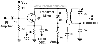
In general terms, a mixer is any circuit that combines two or more circuits or signals into a common output. A more specific definition describes a mixer as a nonlinear circuit that accepts two different frequencies (F1 and F2)...
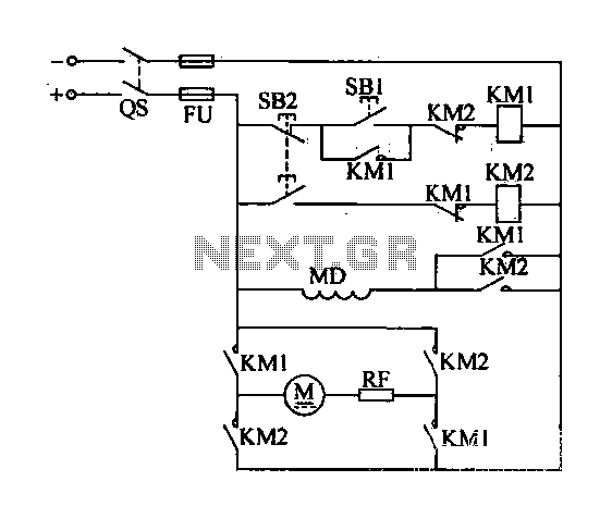
A DC motor reverse brake circuit is presented. To initiate braking, the stop button (SB2) is pressed, which disconnects the move-off contact, causing KM1 to lose power and release. Subsequently, the brake contactor (KM2) is activated. KM2 is designed...