
ECM Mic Preamplifier
The circuit in question is designed to amplify signals from an electret condenser microphone, which is known for its sensitivity and compact size. The selection of low-noise transistors, such as the BC549C or BC109C, is crucial for maintaining a high signal-to-noise ratio, particularly in audio applications where clarity and fidelity are paramount. The self-biasing feature of the circuit allows it to automatically adjust the quiescent point, optimizing performance without the need for manual calibration.
The electret microphone operates effectively within the specified voltage range, ensuring compatibility with various power sources. The use of a 1k resistor to limit current is a standard practice that protects the microphone element from excessive current, while the recommendation to increase this resistor to 2.2k for higher supply voltages ensures that the microphone operates safely within its specifications.
The low output impedance of the circuit enhances its ability to drive long cable runs without significant signal degradation, which is particularly beneficial in professional audio settings. The absence of the need for screened cables simplifies installation and reduces costs, making this circuit suitable for various applications, including live sound reinforcement and recording.
The amplifier's dynamic range is impressive, allowing it to capture both soft and loud sounds effectively. However, it is essential to consider the input characteristics of any connected equipment. Ensuring that the amplifier or tape deck does not overload is critical to maintaining audio integrity and preventing distortion. This design approach ensures versatility and reliability in a wide range of audio environments.Both transistors should be low noise types. In the original circuit, I used BC650C which is an ultra low noise device. These transistors are now hard to find but BC549C or BC109C are a good replacement. The circuit is self biasing and will set its quiescent point at roughly half the supply voltage at the emitter of the last transistor. The electre t condenser microphone (ECM) contains a very sensitive microphone element and an internal FET preamp, a power supply in the range 2 to 10 volts DC is therefore necessary. Suitable ECM`s may be obtained from Maplin Electronics. The 1k resistor limits the current to the mic. This resistor should be increased to 2k2 if a supply voltage above 12 Volts DC is used and is not needed if the Mic insert is dynamic.
The output impedance is very low and well suited to driving cables over distances up to 50 meters. Screened cable therefore is not necessary. The noise response of the amplifier measured across the 10k load is shown below. Please note that this plot was made with the mic insert replaced by a signal generator. This preamplifier has excellent dynamic range and can cope with anything from a whisper to a loud shout, however care should be taken to make sure that the auxiliary equipment i. e. amplifier or tape deck does not overload. 🔗 External reference
Related Circuits
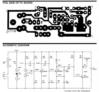
The frequency range for the FM broadcast band is 90 MHz (megahertz, or 90 million cycles per second). An FM microphone utilizes a variable tuned circuit, allowing it to be adjusted to a quiet frequency within the local FM...
This is a simple microphone preamplifier circuit which you can use between your microphone and stereo amplifier. This circuit amplifier microphone suitable for use with normal home stereo amplifier line/CD/aux/tape inputs. This mic preamp can take both dynamic and...
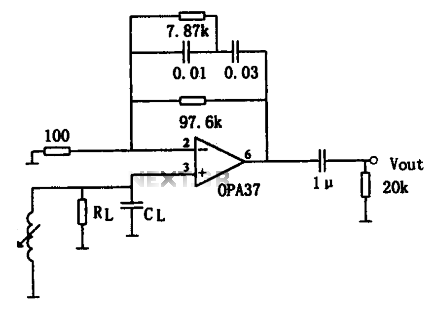
The OPA37 serves as a low-noise preamplifier. The input signal is connected to the inverting input of the OPA37 (pin 3), while the circuit components RL and CL represent the load impedance for electromagnetic pickups. The resistance and capacitance...
This design addresses the limitations of the microphone preamp in the Sony R91, which clips at low levels, providing only 28mV of headroom for an input that may reach 1800mV, depending on the microphone and volume settings. The design...
Connect any I2C client chip (such as temperature sensors, analog-to-digital converters, displays, or relay drivers) to your PC via USB quickly, easily, and affordably. Drivers are available for both Linux and Windows operating systems. The described system facilitates the integration...
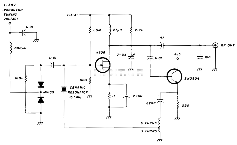
The FET input amplifier utilizes fixed bias with source feedback, resulting in a very high input impedance and low capacitance. An emitter follower is driven by the FET amplifier, which, despite its low output impedance, feeds a transformer with...
Warning: include(partials/cookie-banner.php): Failed to open stream: Permission denied in /var/www/html/nextgr/view-circuit.php on line 713
Warning: include(): Failed opening 'partials/cookie-banner.php' for inclusion (include_path='.:/usr/share/php') in /var/www/html/nextgr/view-circuit.php on line 713