
FM Wireless Microphone

The FM broadcast band operates within the frequency range of 88 to 108 MHz, allowing for a variety of audio transmissions. The FM microphone's variable tuned circuit is essential in ensuring that the microphone can effectively select a frequency with minimal interference, thereby enhancing audio clarity. The conversion of sound into an electrical signal through the microphone element is a critical process that involves transducing mechanical vibrations into electrical changes, which are then processed through the resistor R1. This initial signal undergoes amplification, ensuring that even faint audio signals can be transmitted effectively.
The mini FM transmitter, while operating at a fixed frequency of 12 MHz, simplifies the design and reduces the complexity typically associated with tunable circuits. The use of only two transistors makes it an economical option for hobbyists and those new to electronics. The transmission range of 1/4 mile indicates its potential for various applications, including personal broadcasting and educational demonstrations.
The wireless car alarm system exemplifies practical applications of FM transmission technology. The use of FM radio waves for communication between the transmitter and receiver modules enables reliable operation over a specified range. The voltage requirements of 6-12 VDC ensure compatibility with most vehicle electrical systems, while the inclusion of a voltage stabilizer enhances the circuit's robustness against voltage fluctuations.
The three-stage FM transmitter, capable of reaching distances of up to 1 kilometer, showcases the potential for more powerful and expansive transmission applications. The choice of transistors, such as the RF transistor and BC547, is critical in determining the performance characteristics of the transmitter stages, including gain and frequency response.
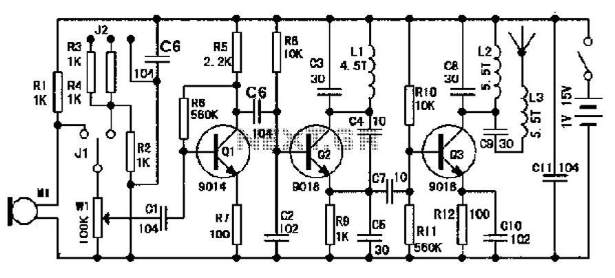
Finally, the multi-stage FM transmitter circuit design illustrates the versatility of FM technology, incorporating various transistors to achieve specific functions such as oscillation, amplification, and transmission. The integration of a condenser microphone at the input stage facilitates direct audio input, making the circuit suitable for a variety of audio transmission applications. Overall, these designs reflect the principles of FM transmission and the potential for innovative applications in wireless communication.The range of frequencies for the FM broadcast band is 90MHz (MHz = Megahertz or 90 million cycles per second). Because the FM microphone has a variable tuned circuit, it can be tuned to a quiet spot on your local FM broadcast band for the best reception.
When the small microphone element is struck by sound, it converts the audio to a change in cu rrent through resistor R1 (see schematic diagram). This electrical change is amplified and eventually frequency modulates the transmitter. The transmission range of the FM microphone is approximately 100 feet, depending on the efficiency of the antenna (properly tuned or not) and the quality of the FM radio receiver. Here the short wave AM Transmitter circuit design diagram. The circuit is quite simple and easy to build since it applies only a few electronic components. The primary feature of this transmitter is that it really is absolutely free from the LC (inductor, capacitor) tuned circuit and runs using a fixed frequency of 12 MHz.
This is a mini FM transmitter built and powered using 2 transistors, designed by Tony van Roon. This small transmitter is simple to build and its transmissions could be picked up on any common FM radio. It possesses a range of approximately 1/4-mile (400 meters) or even more, depending on the line-of-sight, obstructions by big.
This circuit is a wireless car alarm system that is built using two circuit modules, namely modules of transmitter and receiver modules. This circuit works on FM radio waves. Car alarms can be used on vehicles that have a 6-12VDC power supply. You can use the voltage stabilizer if your car power supply is too. This circuit is a powerful three stage, 9V FM transmitter (Tx) with a range of up to 1 kilometer in the open.
It uses an RF transistor in its output stage and two BC547`s for the first two stages. Distance of trans-mission is critically dependent on the operating Conditions (in a building or out on. This is a low cost and easy build low powered FM transmitter. The range of the FM transmitter claimed about 300 feets when running at 9V supply. And the range claimed to be increased become about 400 feet when running it at 12V supply. Take a note that this transmitter should not be used as. This is the FM transmitter circuit which apply 4 radio frequency stages, that are a VHF oscillator designed around transistor BF494 (T1), a preamplifier designed around transistor BF200 (T2), a driver designed around transistor 2N2219 (T3) and also a power amplifier designed around transistor 2N3866 (T4).
A condenser microphone is wired at the input of. 🔗 External reference
Related Circuits
The design of an FM radio transmission frequency band enables compatibility with any FM radio receiver, allowing the high-frequency signal to be transmitted and restored from an audio signal. This technology serves various applications. Applications of a wireless microphone...
This preamplifier uses a type of IC 741 and can boost a microphone signal to line level. The microphone signal is connected to the input port. Any power for the microphone jack of the food are met. Here half...
The power supply is integrated into the base of the microphone, which may cause hum issues, even with the onboard potentiometer designed to nullify this effect. Consequently, the microphone features two cables: one for power and another for audio...
The transmitter circuit for inductive headphones must be installed on a wall or ceiling, limiting their use outdoors. This is a significant drawback of inductive headphones. In contrast, infrared wireless headphones do not have this limitation; their flexible infrared...
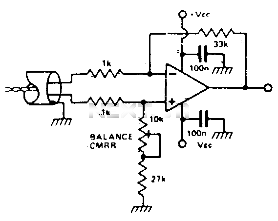
It is possible to simulate the balanced performance of a transformer electronically using a different amplifier. By adjusting the presets, the resistor ratio can be balanced to achieve the best Common Mode Rejection Ratio (CMRR). This method can yield...

A homebrew 2M transceiver was designed for mobile use, eliminating the need for a fist microphone. A low-cost personal hands-free kit for mobile phones was initially considered, but it resulted in inadequate audio performance. The circuit utilized had a...