
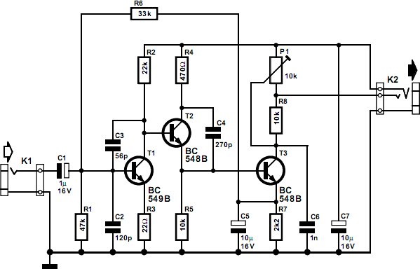
simple stereo electret microphone preamplifier

When selecting an op-amp, it is critical to evaluate the open-loop gain at 20kHz. The circuit offers approximately 27dB of gain, and a minimum of 47dB at 20kHz (20dB higher) is desirable to maintain linearity. The TL072 achieves around 45dB, while the LM833 provides about 55dB, and the NE5532 exceeds 60dB. For compact designs, a single supply rail can be utilized; however, the LM833 is not compatible with this configuration. The TL072 can operate on a single-ended 9V supply, delivering about 1.8VRMS, which is sufficient for the application. Alternatively, two 9V batteries can be employed.
Regarding capacitors, although solid aluminum capacitors are effective, it is recommended to use 1uF film capacitors for both input and output to ensure tighter tolerances and enhanced audio quality. The design aims for substantial headroom, compactness, low noise, affordability, and minimal component count, positioning it between a battery box and a professional-grade device. The leftmost 10k resistor supplies plug-in power to the electret microphone, forming part of the FET amplifier within the electret capsule. This resistor value may range from 2k to 10k, with higher values promoting better stereo separation and lower distortion. The leftmost 2.2uF capacitor blocks bias voltage from the input, creating a high-pass filter in conjunction with the subsequent 27k resistor, with a cutoff frequency close to DC.
The input impedance is determined by two parallel 27k resistors with a 10k resistor, resulting in an effective impedance of approximately 6k. In dual supply configurations, the upper 27k resistor is unnecessary as the input does not require mid-rail biasing. The feedback loop consists of two resistors, 27k and 1.5k, connected from the inverting input to ground. When both resistors are in use, the gain is slightly below 2. The 27k resistor can be bypassed, allowing the 1.5k resistor to set the gain to 23. A 10uF capacitor in the feedback loop reduces DC gain to approximately 1, mitigating any amplified DC input offset that could lead to a larger output offset and decreased headroom. The optional 2pF capacitor in relation to the 33k resistor further refines the circuit's performance.This design was born of frustration with the mic preamp in my Sony R91. It clips at ridiculously low levels, basically it has 28mV of headroom to deal with an input that could be as high as 1800mV (depending on mic & volume), so this design attempts to cure that by : B: Having much greater preamp headroom, and bypassing the R91`s mic preamp altoge ther, using a hi-fi or low noise op-amp to go straight into the line input. The circuit needs to bring the signal from an electret microphone up to a level suitable for a line input. Based on measurement of the microphone output under a range of conditions, I have chosen tw1o gain levels - 2 & 23.
23 is suitable for everyday general recording. 2 is suitable for live music such as a rock concert. There is a output pot to allow fine-tuning of the level if necessary, but it is intended that usually the wiper will be on the land. When choosing an op-amp, it`s important to find out the open loop gain at 20kHz. The circuit has roughly 27dB of gain, and at least 47dB at 20kHz (i. e. 20dB higher) is desirable. This is because op-amp circuits are predicated on an ideally infinite open loop gain, while in reality 10 times (20dB) higher than the closed loop gain at highest frequency of interest is acceptable.
Otherwise the amplifier becomes progressively non-linear. The TL072 at roughly 45dB just makes it. The LM833 is good at »55dB and the NE5532 sparkles at »60+dB. If you`re going for ultra small size, you can build it single supply rail, but an LM833 won`t run like that. A TL072 will, with reduced output swing, it`ll swing about 1. 8VRMS off a single ended 9V supply, which is adequate for the purpose. Otherwise tw1o 9V batteries will do the trick. Now about these solid aluminium capacitors - in some respects very good capacitors, but I think now I would use 1uF film capacitors as input and output capacitors.
They are likely to more closely match the other channel (tighter tolerances), and the golden ear brigade seem to like film capacitors better. So in summary, it`s supposed to have a lot of headroom, be small, quiet, cheap, have a low part count, somewhere betw1een a battery box and a full fledged professional box.
The leftmost 10k resistor supplies plug-in-power to the electret, forming part of the FET amplifier in the electret capsule. This could be anything from 2k to 10k, the higher the better the stereo separation (another mic derives bias from the same rail).
Apparently higher values also lower distortion, and the best bias power circuits involve actually breaking a trace on the electret capsule to allow the use of both a drain & source resistor, but I`m not going that far. The leftmost 2. 2uF cap blocks the bias voltage from the input. In conjunction with the following 27k resistor it forms a high pass filter, but cutoff is essentially near DC.
The input impedance is set by the tw1o 27k resistors and the 10k resistor. The +ve rail is also connected to ground as far as the AC signal is concerned because of the power supply cap. So there are tw1o 27k resistors in parallel, making 13. 5k, in parallel with the 10k, making about 6k or so for the input impedance. But if you`re making it proper dual supply, you don`t need the upper 27k resistor, as the input doesn`t have to be biased mid rail anymore.
The feedback loop has tw1o resistors 27k & 1k5 from the inverting input to ground. When they are both in circuit, the gain is a bit under 2 (28. 5/33)+1). The 27k resistor can be bypassed with a switch, then only the 1k5 sets the gain, to 23 (33/1. 5)+1). The 10uF cap in the bottom half of the feedback loop reduces DC gain to ~1. The value isn`t very important. If any DC input offset were amplified it would create a larger output offset, pushing the output toward one of the rails and reducing headroom. (At a gain of 23 with the expected input levels it probably doesn`t matter. ) The optional 2pF cap in relation to the 33k resistor 🔗 External reference
Related Circuits
Magic Sinewave Analysis using SPICE and a Simple Inverter Circuit. This document discusses the analysis of a sinewave signal generated by a simple inverter circuit using SPICE simulation software. The inverter circuit is designed to convert a DC input voltage...
This simple circuit can be used to activate various devices, such as microcontrollers, relays, secret alarms, or even to turn on LED1, which illuminates as long as a metal plate is touched. The circuit consists of a voltage divider...
This circuit is designed for use with inductive pick-up elements and dynamic microphones. Most soundcards feature a line input and a separate input for electret (condenser) microphones. To connect an inductive tape recorder head or a dynamic microphone, an...

A general-purpose preamplifier/mixer accepts up to four inputs, has a gain of 1600, and provides bass and treble controls that can be varied ± 10 dB at 100 Hz and 10 kHz respectively. More: IC1 and IC2 = LM301A. This...
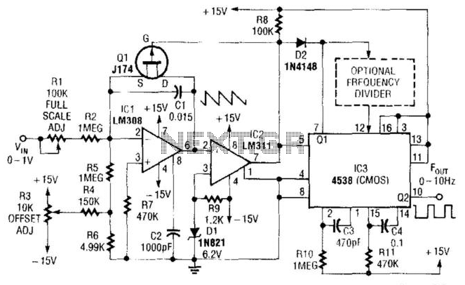
In this circuit, capacitor CI is charged to a fixed reference level and then discharged. The integrator IC1 charges CI until IC1 has a -6.2 V output, at which point comparator IC2 outputs a low signal. FET Q1 triggers...
The circuit was designed to create a modular Class A buffer preamplifier to isolate stages in an audio circuit. BF245 is a general-purpose N-Channel JFET used in this design. The modular Class A buffer preamplifier serves as an essential component...