
ECM microphone preamplifier
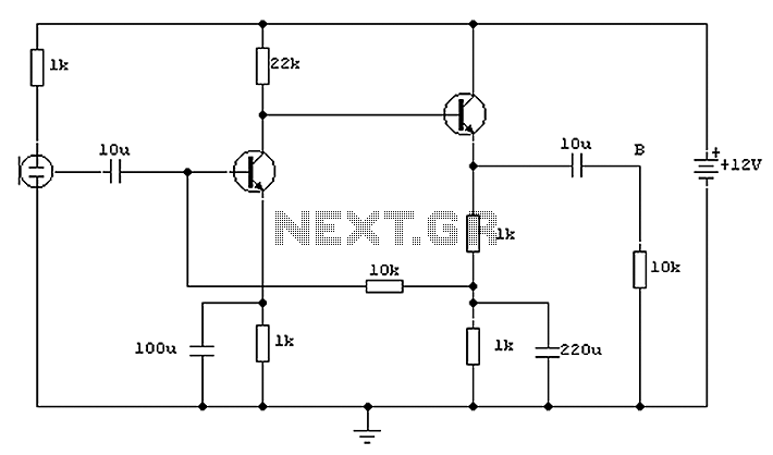
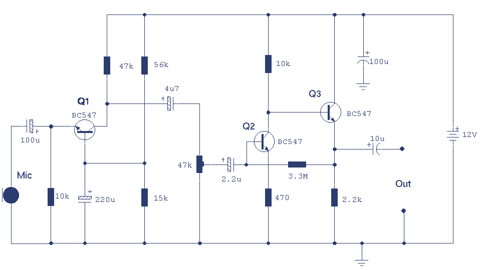
The circuit design incorporates two low-noise transistors, enhancing the overall performance and signal integrity of the audio system. The BC650C transistor, known for its ultra-low noise characteristics, was initially selected for its superior performance in audio applications. The BC109C, as a replacement, retains adequate low-noise performance while being more readily available. The configuration allows for flexibility in device selection without compromising the circuit's functionality.
The quiescent point, set at half the supply voltage, ensures that the final transistor operates efficiently, providing optimal amplification of the audio signal. This design consideration is critical for achieving a balanced output and minimizing distortion during signal processing.
The electret condenser microphone (ECM) plays a pivotal role in capturing sound. Its internal FET preamplifier amplifies the weak signals generated by the microphone element, making it suitable for low-voltage operation. A power supply of 2 to 10 volts DC is required to ensure proper functionality, which can be easily sourced from various power supplies available on the market.
The inclusion of a 1k ohm resistor serves to limit the current flowing to the microphone, protecting it from excessive current that could lead to damage. This resistor is a crucial component in maintaining the integrity of the microphone's operation.
The circuit's output characteristics are designed to accommodate long cable runs, with an output impedance that remains low. This feature allows for the use of standard cables over distances up to 50 meters without significant signal degradation, thus negating the necessity for screened cables. Overall, this circuit design exemplifies an efficient and effective approach to audio signal amplification, ensuring high-quality performance in various applications. Both transistors are low noise types. In the original circuit, I used BC650C which is an ultra low noise device. These transistors are now hard to find but BC109C are a good re placement. The circuit is very device tolerant and will set its quiescent point at roughly half the supply voltage at the emitter of the last transistor.The electret condenser microphone (ECM) contains a very sensitive microphone element and an internal FET preamp, a power supply in the range 2 to 10 volts DC is therefore necessary. Suitable ECMs may be obtained from Maplin Electronics. The 1k resistor limits the current to the mic. The output impedance is very low and well suited to driving cables over distances up to 50 meters. Screened cable therefore is not necessary.
Related Circuits
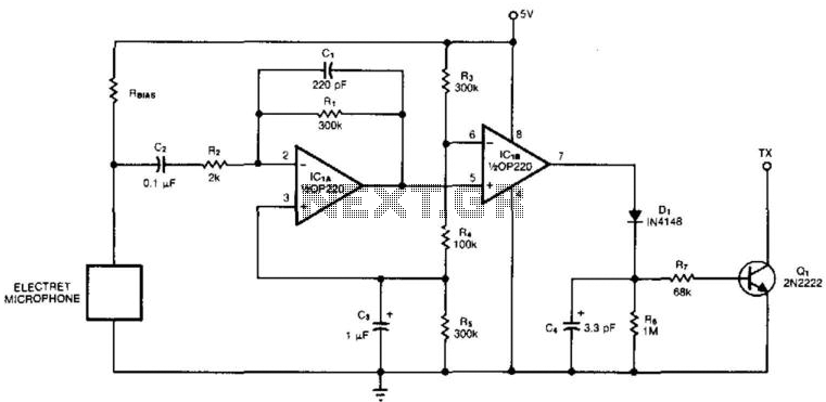
An electret microphone feeds a bandpass filter circuit (IC1A), which subsequently drives a comparator. This comparator activates Q1, a switch that conducts when audio signals from IC1B cause D1, C4, R6, and R7 to bias it ON. The circuit begins...
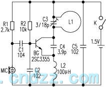
The loop antenna L1 is utilized for emission and also functions as the oscillation coil. The high-frequency current flowing through the antenna is synchronized in resonance with the oscillation frequency, ensuring optimal emission performance. Practical applications indicate that the...
A design was published for a stereo microphone preamplifier featuring balanced inputs and a phantom power supply. The core of this circuit utilizes a specialized analog component. The stereo microphone preamplifier circuit is designed to enhance audio signals captured by...

A general-purpose preamplifier/mixer accepts up to four inputs, has a gain of 1600, and provides bass and treble controls that can be varied ± 10 dB at 100 Hz and 10 kHz respectively. More: IC1 and IC2 = LM301A. This...
This is a 3 stage discrete amplifier with gain control. Alternative transistors such as BC109C, BC548, BC549, BC549C may be used with little change in performance. The first stage built around Q1 operates in common base configuration. This is...

The preamplifier circuit is designed to offer appropriate loading for phono cartridges with reluctance. It achieves a gain of approximately 25 dB at 1 kHz (converting an input of 2.2 mV to an output of 100 mV). The circuit...