
Balanced Microphone Amplifier
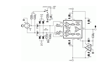
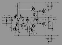
The stereo microphone preamplifier circuit is designed to enhance audio signals captured by microphones while maintaining high fidelity and low noise levels. The balanced inputs are crucial for minimizing electromagnetic interference, which is particularly important in professional audio applications. This is achieved through the use of differential signaling, where two conductors carry the audio signal in opposite phases, allowing for effective noise cancellation.
The phantom power supply is an essential feature that provides the necessary voltage (typically +48V) to condenser microphones, enabling them to function correctly. This power is delivered through the same XLR cables used for the audio signal, simplifying the setup and reducing cable clutter.
The heart of the preamplifier circuit is a specialized analog component, such as an operational amplifier (op-amp) configured for low noise and high gain. This op-amp is selected for its excellent frequency response and low total harmonic distortion (THD), which is critical for maintaining audio quality. Additional components, including resistors and capacitors, are carefully chosen to set the gain levels and filter out unwanted frequencies, ensuring that only the desired audio signals are amplified.
Furthermore, the circuit design may incorporate features such as a high-pass filter to eliminate low-frequency noise and a gain control mechanism to adjust the output level according to the specific requirements of the audio source. The overall layout is optimized for performance, with attention given to the placement of components to minimize signal degradation and interference.
In summary, this stereo microphone preamplifier design is a sophisticated solution for professional audio applications, combining balanced inputs, phantom power supply, and high-quality analog circuitry to deliver superior audio performance.We published a design for a stereo microphone preamplifier with balanced inputs and a phantom power supply. The heart of this circuit was a special Analog.. 🔗 External reference
Related Circuits
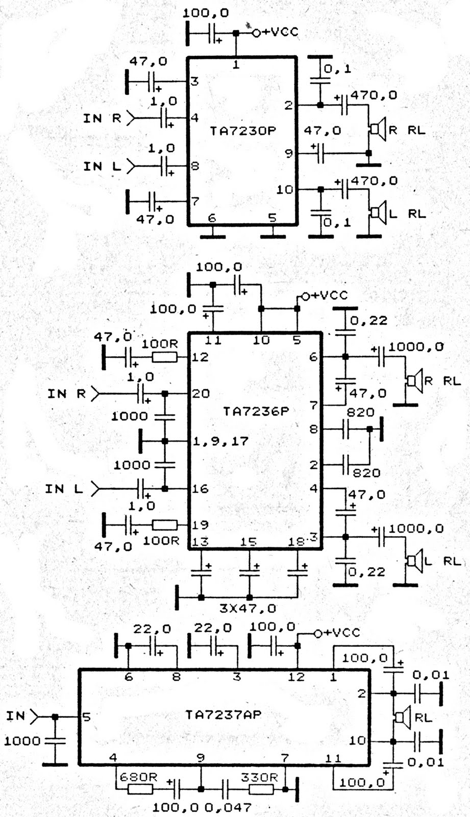
The amplifier circuit is based on integrated circuits (ICs) that determine the gain. Three specific ICs, TA7230P, TA7236P, and TA7237AP, are utilized as power amplifiers. Each IC has distinct output characteristics and input voltage requirements. All three ICs are...
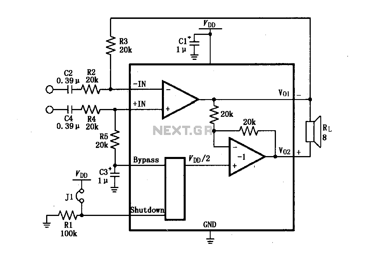
The LM4904 audio input differential amplifier circuit is presented. The audio signal is provided as a differential input to the +IN and -IN terminals. The LM4904 is a low-power audio input differential amplifier designed for high-performance audio applications. This circuit...
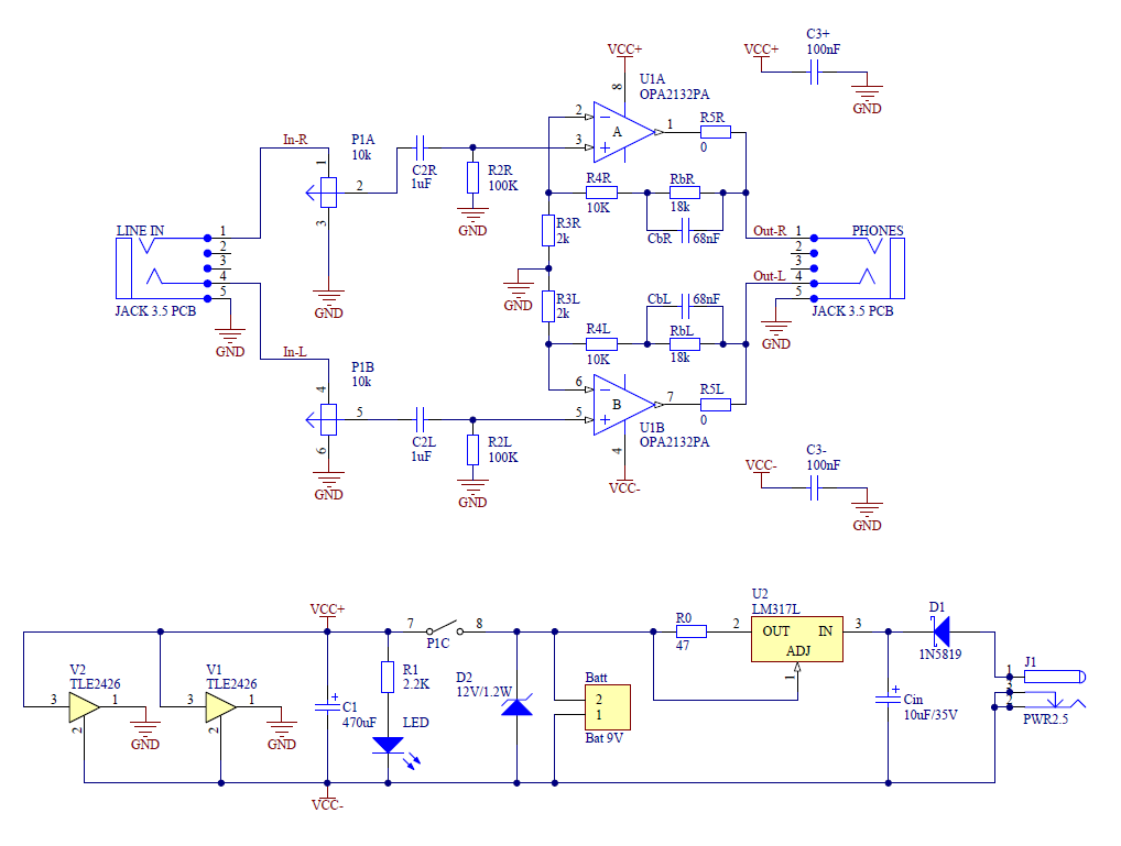
This article discusses a new PCB design for a CMoy headphone amplifier. A key feature of this design is that it fits perfectly into a standard Altoids tin can. The new CMoy amplifier includes a bass-boost circuit and a...
Using this low cost project, one can reproduce audio from a TV without disturbing anyone. It does not use any wire between the TV and headphones. Instead of a pair of wires, it uses invisible infrared light to transmit...
The supply voltage rails were conservatively maintained at +40V and -40V. For those interested in experimentation, the supply voltage can be increased to a maximum of +50V and -50V, enabling the amplifier to reach its target output of 100W...
A 6-watt audio amplifier circuit utilizing the TDA2613 integrated circuit is presented. The TDA2613, produced by Philips Semiconductors, is a high-fidelity audio amplifier IC. This component is designed to be click-proof when switched on or off, resistant to short...