
Economical Desk Lamp For Camping
This LED lamp circuit is tailored for efficient operation within a solar-powered 12V system, making it suitable for environments where energy conservation is essential. The design employs six high-brightness white LEDs, arranged in two parallel banks of three LEDs in series, ensuring adequate illumination for reading tasks at night. The use of a 90mm diameter reflector, such as the upper half of a stainless steel ice cream bowl, enhances the light output by directing and concentrating the emitted light, thereby improving the overall efficiency of the lamp.
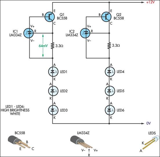
The LED configuration operates at a nominal voltage of 12V, with each LED exhibiting a forward voltage drop of approximately 3.2V. This results in a total voltage drop of 9.6V across the three LEDs in series, leaving a sufficient voltage across the current regulation components. To maintain consistent brightness regardless of battery voltage fluctuations, the circuit incorporates an LM334 current source IC paired with a BC558 transistor. The LM334 serves as a constant current driver, ensuring that each LED receives a stable current of 20mA, which is critical for maintaining brightness and prolonging LED lifespan.
The circuit's operation hinges on the LM334's ability to regulate the base current of the BC558 transistor, which in turn controls the current flowing through the LED string. The 3.3Ω resistor is essential for establishing the desired current level, as it enables the LM334 to develop a reference voltage of 64mV between its "R" and "V-" terminals, facilitating precise current control.
The physical assembly of the circuit can be accomplished on a small piece of Veroboard, providing a compact and organized layout for the components. An old desk lamp serves as an effective housing for the circuit, with a metal disc covering the opening left by the removal of the original 240V lamp fitting. This disc not only seals the lamp but also provides a mounting point for the power switch and rubber grommet, which accommodates the power supply leads. To secure the reflector in place, three M3 screws and nuts are positioned 120° apart, ensuring stability and alignment of the light source. This thoughtful design not only enhances functionality but also promotes ease of assembly and maintenance.This LED lamp was originally designed for use on a budget solar-charged 12V electrical system. It is bright enough for comfortable reading at night and features constant LED brightness with diminishing battery voltage. The circuit uses six high-brightness white LEDs mounted in a 90mm diameter reflector. The upper half of a stainless steel ice crea m bowl makes a good reflector but almost any torch reflector of a similar size will do. As shown, two banks of three series-connected LEDs are powered from a 12V (nominal) DC supply. The LEDs used are rated at 20mA maximum with a measured voltage drop of 3. 2V. Each bank combines an inexpensive LM334 current source IC with a BC558 transistor to provide a constant 20mA to the LED string. Basically, the LM334 controls the base current of the BC558 such that 64mV appears between its "R" and "V-" terminals.
With the 3. 3O resistor shown, this results in close to the desired 20mA through the LEDs. The components can be mounted on a small piece of Veroboard. An old desk lamp makes an ideal body, with a metal disc used to cover the hole left after the 240V lamp fitting is removed. The metal disc can also be used to mount the power switch and rubber grommet for the power supply leads.
Three M3 screws and nuts spaced 120 ° apart keep the reflector in place. 🔗 External reference
Related Circuits

The circuit operates based on the principle that neon tubes N1, N2, and the photosensitive resistor RG1 form an optocoupler. When a finger touches the metal sheet S1, N1 lights up, causing RG1's resistance to decrease. This reduction allows...

Fluorescent tubes consume significantly less energy compared to incandescent lamps and have a much longer lifespan. They provide diffuse, glare-free lighting and generate low heat output. These attributes make fluorescent lighting a preferred option in commercial and retail environments,...

This disco lamp circuit is not a voice-operated switch (VOX) because it cannot differentiate between musical sounds and human voices. Instead, it is sound-activated. An interesting application of this circuit is to control disco lighting automatically using the musical...

To create a telephone ring monitor, it is sufficient to connect a resistor in series with a bulb and plug it into a main outlet. The resistance value of this resistor may vary depending on the type of bulb...

The circuit was designed to experiment with using small fluorescent lamps as a broad pattern source of modulated light. The circuit delivers narrow 1 μs pulses to the small lamp at a frequency of 10 kHz. Each pulse generates...

This circuit gradually illuminates a 120VAC lamp over an approximate 20-minute period. A bridge rectifier converts the AC voltage to 120V DC, supplying power to the MOSFET and the 60-watt lamp. A 6.2K, 5-watt resistor along with a Zener...