
220 Volt Disco Lamp circuit

The disco lamp circuit operates based on sound activation rather than voice recognition. The core of the circuit comprises a microphone that captures ambient sound, which can be either a moving coil or a condenser type. The choice between these microphones depends on the desired sensitivity and frequency response, with condenser microphones generally offering a broader range and better sensitivity to subtle sounds.
Upon capturing sound, the microphone converts acoustic energy into an electrical signal. This signal is then fed into a pre-amplification stage, which is critical for boosting the weak microphone signal to a usable level. The potentiometer in this stage allows for fine-tuning of the gain, enabling the user to adjust the sensitivity of the circuit based on the ambient noise level or the specific requirements of the application.
The amplified signal is then processed to determine if it exceeds a certain threshold, which indicates that a significant sound event, such as music, is occurring. When the signal surpasses this threshold, it triggers a relay that controls the power to the disco lights. The relay acts as a switch, turning the lights on or off in response to the detected sound level.
To ensure reliable operation, it is essential to use an electrolytic capacitor rated for at least 16 volts, which is crucial for filtering and stabilizing the power supply to the circuit components. Proper capacitor selection helps to prevent damage from voltage spikes and ensures consistent performance.
In summary, this circuit provides an effective method for synchronizing lighting effects with music, creating an engaging atmosphere in various settings such as parties or events. The design is straightforward, making it accessible for hobbyists and electronics enthusiasts who wish to enhance their audio-visual experiences.This disco lamp circuit is not a voice operated switch (VOX) because this circuit is too dumb to differentiate between musical sound or human voice. This is rather a sound activated than voice activated. One interesting application is to control your disco lighting automatically by the musical sound from high power amplifier, when the music signal
is dominating the sound space. The disco lamp circuit schematic diagram is shown below. You can use either moving coil microphone or condenser microphone for this circuit. Make sure the electrolytic capacitor is rated for 16 volt or more. The potentiometer shown in the schematic diagram is used to adjust the gain of the pre-amplification. You can adjust this potentiometer to get a proper sound level where the relay would be activated. 🔗 External reference
Related Circuits
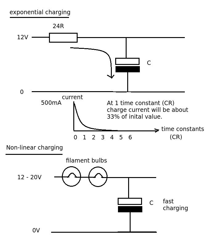
Designing a simple current limiter that charges a large 4.7mF capacitor with a charge current of approximately 500mA from a supply voltage of 10-20V. The dilemma is that there are existing MMBT2222A transistors available, which would be preferable to...
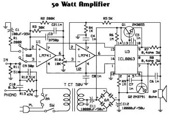
An audio amplifier is an electronic device designed to amplify low-power audio signals, which primarily consist of frequencies ranging from 20 Hz to 20,000 Hz, the human range of hearing. This amplification is necessary to drive loudspeakers and represents...
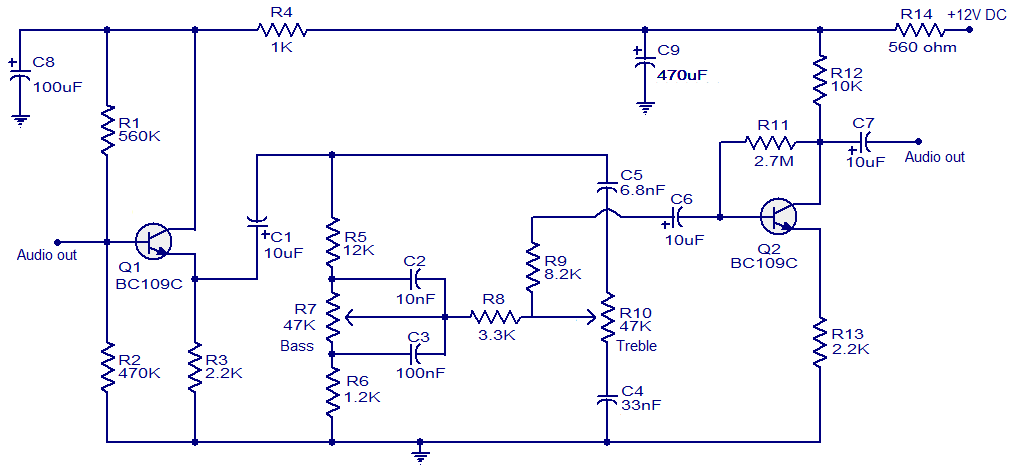
This simple tone control circuit is designed based on the renowned Baxendall tone control circuitry. The circuit can provide a maximum cut or boost of approximately 12 dB at both 10 kHz (treble) and 50 Hz (bass). Additionally, both...
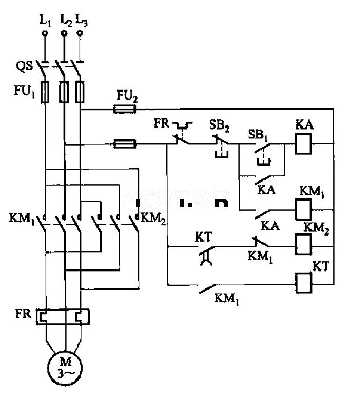
The circuit illustrated in Figure 3-127 utilizes a time relay (KT) in place of a speed relay. The timing duration is adjustable and typically set between 1 to 2 seconds. This circuit is designed to operate effectively in dusty...
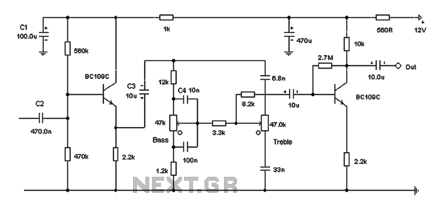
Based on the classic Baxendall tone control circuit, this design offers a maximum cut and boost of approximately 10 dB at 10 kHz and 50 Hz. Since the controls are passive, the final transistor provides a slight boost. The...
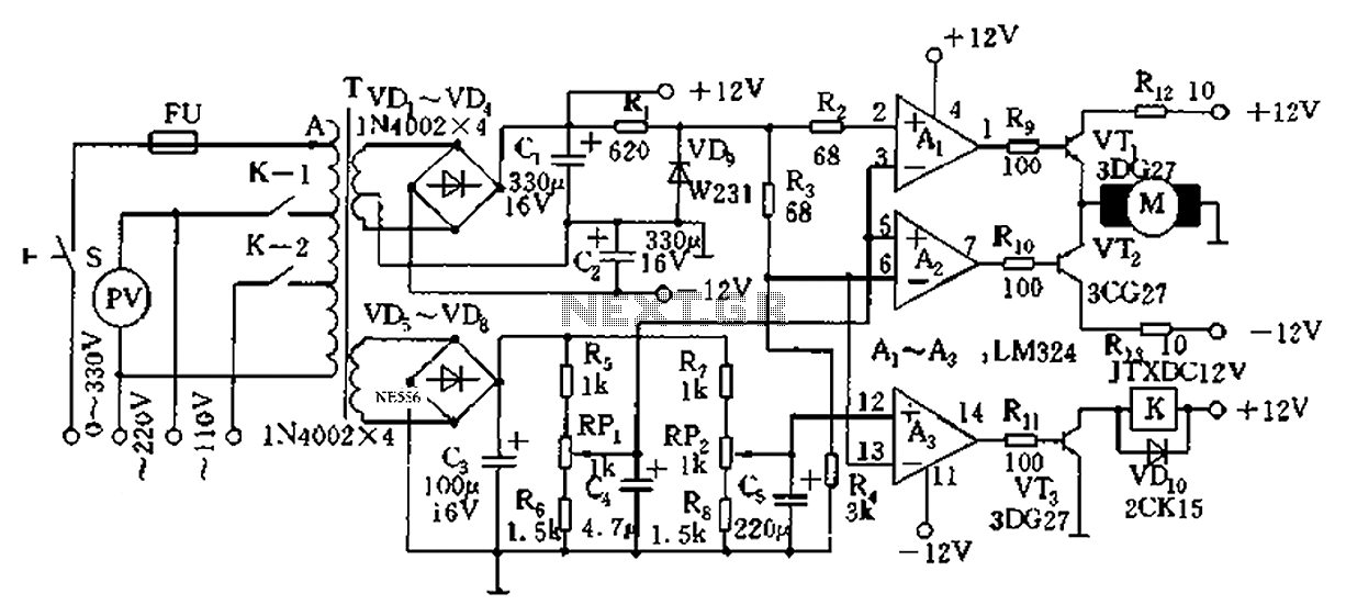
Automatic AC voltage regulator circuit TXD1742 with continuous adjustment. The TXD1742 is an automatic AC voltage regulator circuit designed to provide continuous voltage adjustment, ensuring stable output voltage in varying load conditions. This circuit is particularly useful in applications where...