
Lamp touch switch circuit diagram

The circuit design employs a straightforward optocoupler configuration that utilizes neon tubes and photosensitive resistors to achieve a touch-sensitive control mechanism for an AC-powered load. The operation begins with the activation of N1 when a finger makes contact with the metal sheet S1. This contact causes N1 to emit light, which reduces the resistance of RG1, thereby allowing sufficient current to flow through the gate of triac VS1. As VS1 turns on, it energizes the load, represented by bulb H.
The circuit remains in this active state due to the feedback loop created by the illumination of N2, which continues to light up as long as H is on. The light from N2 keeps RG1's resistance low, ensuring that VS1 remains triggered even after the initial contact with S1 is removed. This characteristic allows for sustained operation of the load without requiring continuous contact.
The second part of the circuit involves the interaction with S2. When H is lit and S2 is touched, N3 activates, leading to a decrease in the resistance of RG2. This action triggers triac VS2, which effectively turns off VS1 by interrupting the current flow to the gate. Consequently, the load H is de-energized, completing the control cycle initiated by the user.
The neon tubes used in this circuit operate at a striking voltage of approximately 60V, making them suitable for low-power applications. The load, bulb H, is rated for less than 100W, ensuring that the circuit remains efficient and safe to operate. The copper sheets S1 and S2, sized at 5mm by 5mm, provide adequate surface area for reliable touch detection without requiring complex components or circuitry.
Overall, the simplicity of the circuit design allows for easy assembly and troubleshooting, making it an effective solution for touch-sensitive applications in various electronic projects. The use of readily available components further enhances its accessibility for hobbyists and engineers alike. Circuit principle as shown, neon tubes N1, N2 and photosensitive resistance RG1 constitute an optocoupler. When touching the metal sheet S1 with a finger, N1 light, so RG1 resi stance becomes smaller, so the triac VS1 because sufficient trigger current conduction, so the bulb H energized and lights. At the same time, 220V AC voltage H on the N2 so light, of course, this light shone on RG1, so this time, even touch-up, VS1 remains in the conductive state, namely H remains lit.
FIG neon N3 and photosensitive resistor RG2 constitute another photoelectric coupling device. H lit, if you touch a metal sheet S2, the N3 light, so RG2 resistance becomes smaller, the TRIAC VS2 due to sufficient trigger current conduction, so that its G VS1 pole and T1 extremely short and off, H off. To sum up: touch the S1, H lit; then touch the S2, H off; again and again. N1, N2, N3 with a striking voltage of about 60V neon tube lamp power is less than 100W, S1 and S2 for the copper, the size of 5mm 5mm.
No special requirements other components. The entire circuit structure is simple, as long as the correct assembly and welding, debugging can work properly.
Related Circuits
%2Band%2B(US)%2BCX500%2BC%2B1979-81%2Band%2B1979%2BCX500%2BD%2BElectrical%2BWiring%2BDiagram.jpg)
Lamp Electrical Circuit Diagram Manual PDF Download. This document provides a comprehensive manual for downloading the electrical circuit diagram of a lamp. The circuit diagram serves as a crucial reference for understanding the electrical connections and components involved in lamp...

A zero-crossing detector converts an input sine wave (Vin) into a square wave, which, when high, charges an op-amp integrator. A reference-input square wave subsequently discharges the integrator. The output voltage of the integrator at the end of this...

Wireless audio and visual transmission to a TV. The TV functions as a receiver, eliminating the need for a separate monitor. It can also be connected to a VCR or CCD camera, enabling the setup of a remote CCTV...

The following circuit illustrates the SciTech PS-3R Power Supply Circuit. Features include 13.8V DC output, 5 Amps surge capability, and a constant output of 3 Amps. Components include a transistor and others. The SciTech PS-3R Power Supply Circuit is designed...
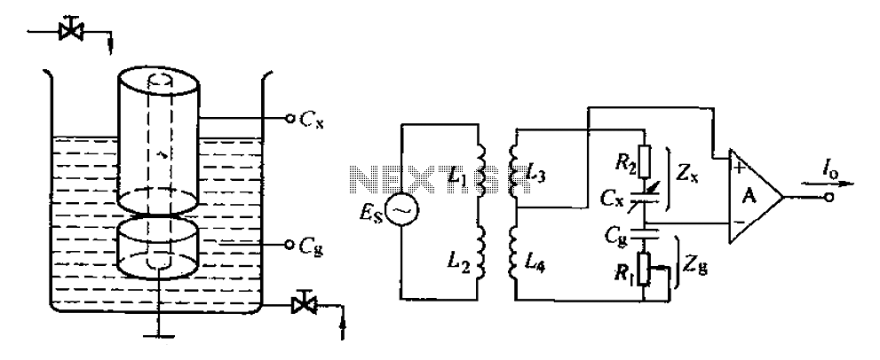
The capacitance change in a capacitive sensor is directly converted into electrical parameters, which are then unified for signal transmission, processing, and display. These electrical parameters can be categorized into resistive, capacitive, and inductive types. This explanation focuses on...
This is a schematic diagram of a stereo audio amplifier for a car. The circuit is powered by a single IC, the TDA1553, along with some external components. This IC is designed to manage the stereo car audio system....