
el cheapo cable tester
The cable tester circuit operates on a simple principle of voltage division and continuity checking. The circuit is designed to test the integrity of connections within a cable by utilizing a series of resistors to create a voltage divider network. Each resistor in the ladder corresponds to a specific pin in the connector, allowing for individual pin testing.
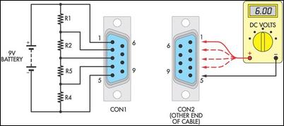
To construct the tester, the following components are necessary: a 9V battery, two D-9 connectors (or any other suitable connectors), a selection of resistors (preferably between 1kΩ and 50kΩ), and a multimeter. The battery clip is soldered to the two pins on one of the connectors, establishing the power source for the circuit. The resistors are connected in series between the power and ground connections, with each resistor leading to a different pin on the connector.
When testing a cable, the user connects the cable under test to the second D-9 connector. By applying the 9V battery and measuring the voltage at the corresponding pins on the opposite connector with a multimeter, it is possible to determine the condition of each connection. A reading close to 9V at a pin indicates a good connection, while a significantly lower voltage suggests a potential issue such as a short circuit, open circuit, or incorrect wiring.
This method is particularly useful for troubleshooting and verifying the integrity of multi-core cables in various applications, providing a reliable and low-cost solution for cable testing.Many cable testers have been published before, some quite complex, but here`s a cheap and simple alternative. It uses only a 9V battery, two mating connecators and a few resistors, as well as a multimeter for voltage measurements.
Begin by soldering the leads of a 9V battery clip between the two pins furthest apart on one of the test connectors an d then add a ladder of resistors between them for each of the other required pins. Any junk-box resistors will do but values between 1k © and 50k © are best. In the example shown, a five-core data cable terminated with D-9 connectors is to be tested. Connect 0V to pin 5, +9V to pin 1, and four resistors in between. Plug in a 9V battery and then probe the connector at the other end of the cable with a multimeter as indicated. Broken, shorted or incorrect connections are all quickly evident using this method. 🔗 External reference
Related Circuits
A simple Zener diode tester circuit, when combined with a PWM generator, can be utilized to measure the breakdown voltage of Zener diodes. More generally, it can also measure the breakdown voltages (e.g., BVceo, BVcbo) of BJTs (Bipolar Junction...
This little guide for every electronics tester would actually have to lie in the toolbox. You can have components such as resistors, capacitors, diodes, etc. of testing. T1 and T2 form a Darlington. Therefore only need a small base...
The CCFL tube is powered by a small electronic inverter circuit (CCFL inverter) that illuminates the screen electronically. This inverter circuit accepts a low-level DC input voltage and provides a high-level AC output to operate the backlight CCFL tube(s)....
Tools that feature the equivalent of a professional, easy-to-use, cheaper, and, more importantly, safe for use. They are designed for checking and identifying AC voltages of 220 Volt or 120 Volt. The tools mentioned are essential for ensuring electrical safety...
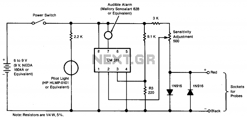
The tester provides an audible indication, eliminating the need for the user to directly observe a meter reading. Additionally, the current and voltage output of the tester are strictly limited, with a maximum of 0.6 volts DC and 3...
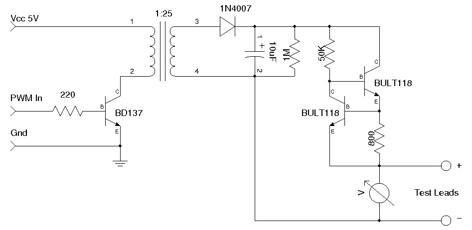
This circuit utilizes a single 555 Timer IC along with a small transformer to generate high voltage for testing zener diodes with voltage ratings up to 50VDC. The 555 timer operates in astable mode, with the output from pin...