
Conductivity Tester circuit
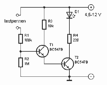
R1 = 100 kΩ
R2 = 1 MΩ ½
R3 = 10 kΩ
R4 = 220 Ω
D1 = LED red
T1, T2 = 547 BC
The described circuit functions as a basic electronic tester for resistors and capacitors, leveraging a Darlington pair configuration formed by transistors T1 and T2 (BC547). This configuration allows for high current gain, enabling the circuit to operate effectively even with minimal base current. The presence of the LED (D1) provides a visual indication of the circuit's operational status.
In the testing mode for resistors, the circuit can accommodate resistances up to 2 MΩ. When a resistor is connected across the leads, the current flowing through the resistive element causes the LED to light up, confirming the functionality of the resistor. Resistor R1 (100 kΩ) serves as a current-limiting resistor for the LED, ensuring that it operates within safe limits.
For capacitor testing, the circuit is designed to briefly illuminate the LED when a capacitor is connected. The duration of the LED's illumination depends on the capacitor's value; larger capacitances will result in a longer discharge time, causing the LED to remain lit for a more extended period before extinguishing. It is essential to note that electrolytic capacitors have polarity, and incorrect connections may lead to erroneous readings or damage.
Resistor R2 (1 MΩ) is utilized to provide a discharge path for the capacitor, while R3 (10 kΩ) and R4 (220 Ω) are included to stabilize the circuit and set the appropriate biasing conditions for the transistors in the Darlington pair. The sensitivity of the circuit is such that even slight contact between the test leads can cause the LED to illuminate, indicating the high gain characteristic of the Darlington configuration.
This electronic tester is a valuable tool for hobbyists and professionals alike, providing a compact and efficient means to test basic electronic components directly from a toolbox.This little guide for every electronics tester would actually have to lie in the toolbox. You can have components such as resistors, capacitors, diodes, etc. of testing. T1 and T2 form a Darlington. Therefore only need a small base current to run and the LED is already lit. The tester is suitable for up to 2 M? resistors. The tester is also suitable for capacitors. When a capacitor is connected to the leads, the LED, depending on capacity, light briefly and then to extinguish. When electrolytic capacitors have polarity. The circuit is so sensitive that even the LED lights when the contacts between the fingers touched. Note that this does not happen during testing. R1 = 100 kOhm R2 = 1 M ½ R3 = 10kW R4 = 220 ? D1 = LED red T1, T2 = 547 BC 🔗 External reference
Related Circuits
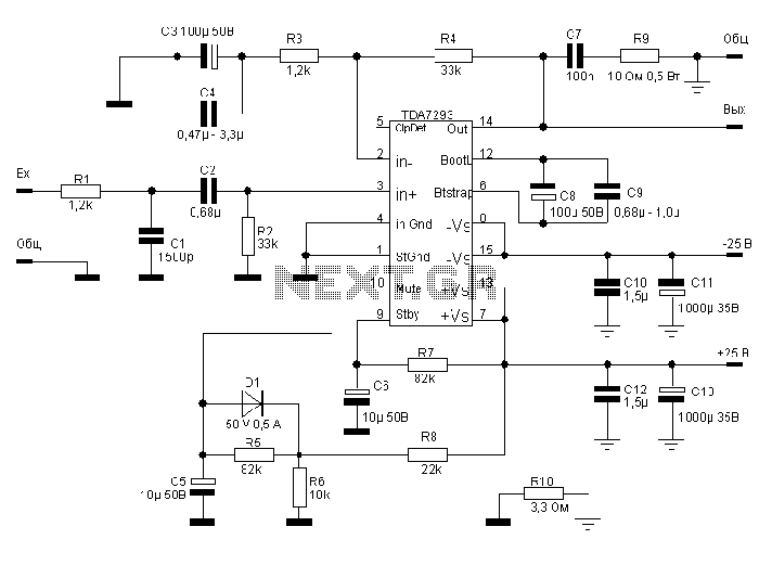
The TDA7293, produced by the ST (SGS-THOMSON) company, is a high-power, high-voltage DMOS high-fidelity amplifier integrated circuit (IC) with a rated output power of 100W. It operates at a maximum voltage of 120V. The key specifications include a dual...
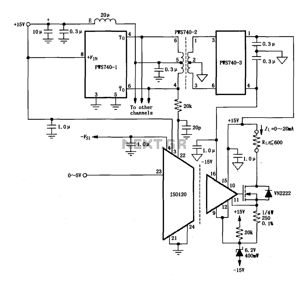
An eight-channel isolation circuit is constructed using the ISO120 and PWS740 components, designed for a 0 to 20 mA current loop. The figure illustrates only one channel, where the circuit converts a 0 to 5V input voltage into a...
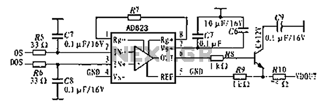
The AD623 is an integrated 3-way amplifier that can operate with either a single or dual supply. It features high common-mode rejection ratio (CMRR) and low voltage drift, along with programmable gain control via an external resistor. All components...
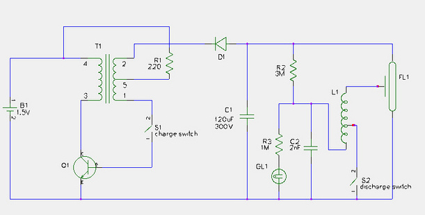
This document provides a step-by-step guide for modifying a disposable camera flash unit to serve as a power supply for a Geiger tube. The process involves removing the flash tube and trigger transformer from the circuit board by gently...
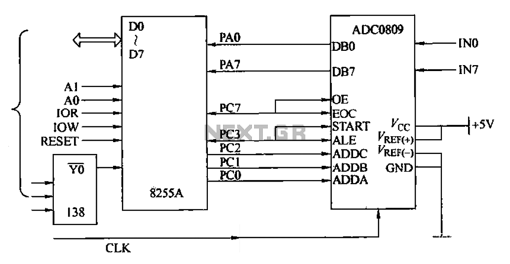
The ADC0809 is an 8-channel analog switch integrated with an 8-bit successive approximation analog-to-digital (A/D) converter. It supports the selection of eight input channels through address latch and encoder channel selection signals ADDA, ADDB, and ADDC. The address latch...
Switching regulator subsystems intended for use as DC to DC converters. 3V to 40 Volt DC Converter circuit. The use of switching regulators is becoming more pronounced than that of linear regulators because the size reductions in new equipment...