
Zener Diode Tester Test Gears Circuits Schematics
This circuit design effectively demonstrates the use of the 555 Timer IC to create a high-voltage test environment for zener diodes. The astable configuration of the 555 timer generates a square wave output, which is essential for driving the audio transformer. The LT700 transformer is specifically selected for its impedance characteristics, allowing it to efficiently convert low-voltage signals into high-voltage AC output.
In the circuit, the primary winding of the transformer is connected to the output of the 555 timer, while the secondary winding is utilized to produce the high voltage. The unloaded AC voltage of approximately 120 volts AC is suitable for testing zener diodes, as it exceeds the maximum rating of 50VDC, allowing for effective testing of breakdown characteristics.
The output AC voltage is then rectified by the 1N4004 diode, which is a standard rectifier diode capable of handling the voltage and current levels involved in this application. Following rectification, the voltage is smoothed by the 2.2 µF capacitor, which is crucial for reducing ripple and providing a stable DC voltage for the zener diode test. The capacitor must be rated for at least 150 VDC to ensure safety and reliability during operation.
The circuit also incorporates a load current switch that enables the user to set the test current through the zener diode to either 1 mA or 2 mA DC. This feature is important for evaluating the zener diode's behavior under different load conditions. The multimeter, set to measure DC voltage, provides a clear indication of the zener diode's performance. A properly functioning zener diode will maintain a constant voltage reading on the multimeter, signifying its ability to regulate voltage effectively.
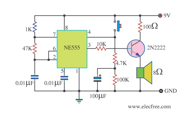
Overall, this circuit serves as a practical and efficient method for testing the operational integrity of zener diodes, ensuring that they meet their specified voltage ratings.Using a single 555 Timer IC and a small transformer to generate a high voltage, this circuit will test zener diodes of voltage ratings up to 50VDC. The 555 timer is used in the astable mode, the output at pin3 drives a small audio transformer such as the LT700.
This has a primary impedance of 1K and a secondary impedance of 8 ohms. Used in reverse the unloaded ac voltage is around 120volts ac. This is rectified by the 1N4004 diode and smoothed by the 2. 2u capacitor which MUST be rated at 150 VDC. The zener under test is measured with a multimeter set to DC volts as shown. The load current switch enables the zener to be tested at 1 or 2mA DC. The rectified DC load, but a good zener should maintain the reading on the volt meter. 🔗 External reference
Related Circuits
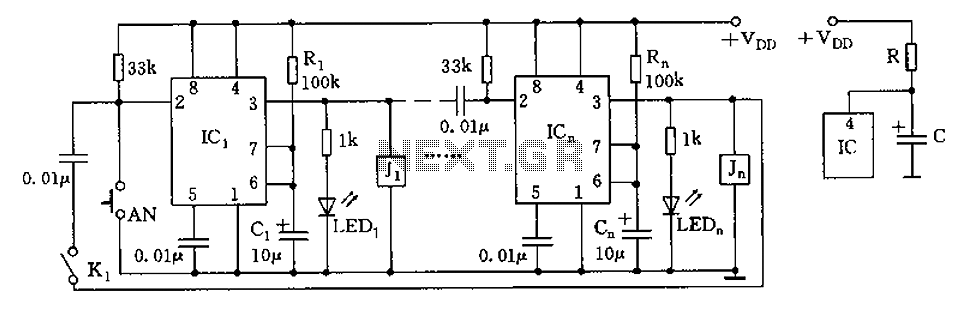
Imagine encountering numerous cable ends that are all identical in color and lack any form of identification. The opposite ends of these cables are located in a different part of the building, making it impossible to determine their connections....
The circuit depicted in the figure is designed for multi-temperature testing, allowing for the switching of the thermocouple corresponding to the active channel. At the core of this design is a 555 timer configured in a monostable delay mode....
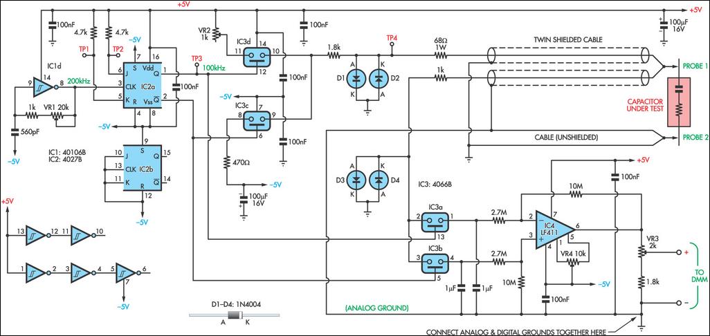
As electrolytic capacitors age, their internal resistance, known as "equivalent series resistance" (ESR), gradually increases, potentially leading to equipment failure. This design allows for the measurement of the ESR of suspect capacitors as well as other small resistances. The...
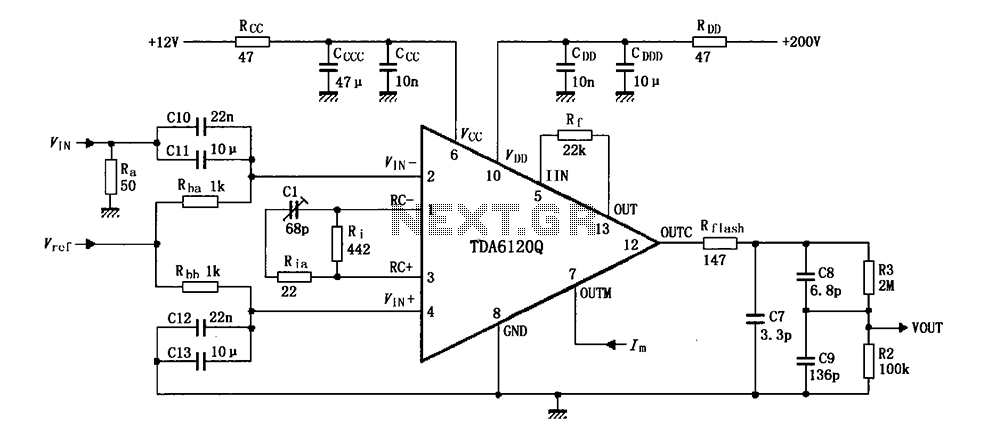
Feedback has indicated that the TDA6120Q test circuit, as shown in the figure, utilizes an input signal (Vi) composed of resistors Ra and capacitors C10 and C11, which are fed into the TDA6120Q at pins 2, 3, and 4....
This is a danger beep circuit. It uses a 555 integrated circuit configured as a stable multivibrator that provides a duty cycle of 5% to drive a loudspeaker. The danger beep circuit utilizes the 555 timer IC, a versatile and...

The TPS61200 specifications indicate that GND serves as the control/logic ground, while PGND is designated as the power ground. However, this distinction is not accurately represented in the symbols used in the diagram. There is also confusion regarding the...
Warning: include(partials/cookie-banner.php): Failed to open stream: Permission denied in /var/www/html/nextgr/view-circuit.php on line 713
Warning: include(): Failed opening 'partials/cookie-banner.php' for inclusion (include_path='.:/usr/share/php') in /var/www/html/nextgr/view-circuit.php on line 713