
EL Lamp Driver Using HV832MG
As an AC voltage is applied to the electrodes, the electricaleld causes the phosphor to rapidly charge and discharge, resulting in the emission of light during each cycle. Since the number of light pulses depends on the magnitude of the applied voltage, the brightness of EL lamps can generally be controlled by varying the operating voltage.
Because EL lamps are a laminate, they exhibit a capacitance of the order of 2. 5 nF to 3. 5 nF per square inch. When high voltage is applied across the electrodes, the resulting electriceld excites the phosphor atoms to a higher energy state. When the electriceld is removed, the atoms fall back to a lower energy state, emitting photons in the process.
The wavelength of the emitted light is determined by the type of phosphor used and the frequency of the excitation voltage. With most phosphors, the spectrum of emitted light will tend to shift towards blue with an increase in excitation frequency.
Color is usually controlled, however, by selecting the phosphor type, by adding fluorescent dyes in the phosphor layer, through the use of a color filter over the lamp, or a combination of these. EL lamp brightness increases approximately with the square of applied voltage. Increasing frequency, in addition to affecting hue, will also increase lamp brightness, but with a nearly linear relationship.
Most lamp manufacturers publish graphs depicting these relationships for various types of lamps. Excitation voltages usually range from 60 VPP to 200 VPP at 60 Hz to 1 kHz. Increased voltage and/or frequency, however, adversely affects lamp life, with higher frequencies generally decreasing lamp life more than increased voltage. EL lamps, unlike other types of light sources, do not fail abruptly. Instead, their brightness gradually decreases through use. For intermittent use, lamp life is seldom a concern. For example, if a lamp is used 20 minutes per day, over the course of 10 years the lamp will be activated for a total of 1, 216 hours, well within the useful life of almost any EL lamp available.
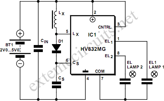
When designing a drive circuit, a balance needs to be struck between lamp brightness, hue, useful life, and supply current consumption. To generate the high voltages needed for driving EL lamps, dedicated ICs like the Supertex HV832MG employ switch-mode converters using inductive‚yback.
By integrating high voltage transistors on-chip, this driver avoids the need for expensive, bulky, and noisy transformers to generate high output voltages. The HV832MG employs open-loop conversion. This EL driver incorporates a lamp drive oscillator that is separate from the power conversion oscillator.
This allows setting lamp drive frequency independently from the power conversion frequency and so optimize overall performance. The power conversion cycle begins when a MOSFET switch in the HV832MG is turned on and current begins to rise in inductor Lx.
When the switch is turned off, inductive‚yback causes the voltage across the inductor to reverse polarity and rise until it reaches the level of the storage capacitor CS, (plus diode drop) at which point the rectifier conducts and the energy contained in the magneticeld of the inductor is transferred to CS. When all the inductor energy is transferred and inductor current drops to zero, the rectifier stops conducting and inductor voltage drops to zero, ready for the next cycle.
Output power is simply the amount of energy transferred per cycle multiplied by the number of cycles per second. It is important to select the inductor and conversion frequency to provide the required output voltage while assuring that the inductor current does not approach saturation levels.
If the inductor saturates, excessive current will flow, potentially leading to device failure. Ideally, the inductor current should be allowed to return to zero between cycles. If inductor current is not allowed to return to zero, a higher average current will be needed to meet output power requirements, increasing I2R losses, and decreasing conversion efficiency. On he other hand, if too much time is allowed between zero inductor current and the start of the next cycle, more energy will need to be transferred each cycle to maintain output power, thus risking inductor saturation and increasing I2R and core losses.
This circuit provides an output of 130 volts at 300-450 Hz, draws just 30mA current, yet is capable of driving EL lamps with a surface area of up to 9 cm2. This design has excellent drive capability and provides a symmetrical bipolar drive, resulting in a zero-bias signal.
Many lamp manufacturers recommend a zero-bias drive signal to avoid potential migration problems and increase lamp life. The supply voltage should be bypassed with a capacitor located close to the lamp driver. Values can range from 0. 1 µF to 1 µF depending on supply impedance. For very large lamps representing much larger capacitances, a FET follower circuit may be employed to boost the output drive capability of the lamp driver.
The HV832MG may be obtained from Supertex Semiconductors, USA, 🔗 External reference
Related Circuits
The main features of the MULTIWATT Package, a trademark of SGS-THOMSON Microelectronics, include a power amplifier IC designed specifically for car radio applications. It offers a high current capability of 3.5A and can drive a very low impedance of...
The provided schematic diagram illustrates an LM741 light/dark sensor circuit, derived from the 741 Op-Amp Tutorial by Tony van Roon. The ECG128/NTE128 transistor can be replaced with any NPN transistor that meets the necessary gain and current specifications for...
Pulse width modulation, commonly referred to as PWM, is utilized to regulate the power supplied to a load without sacrificing efficiency. This technique is often employed in controlling the speed of an electric motor. PWM operates by varying the width...

Illuminate your tabletop with this stylish White LED Lamp. It is powered through a USB port, making it perfect for taking notes while browsing the internet. The USB port can provide a convenient power source. The White LED Lamp is...

This light sensor circuit, utilizing a photosensor, serves as a bridge between light and electronics. It is constructed using an operational amplifier and the PIC16C63 microcontroller to control the sensor. While the circuit is not intended for precision applications,...
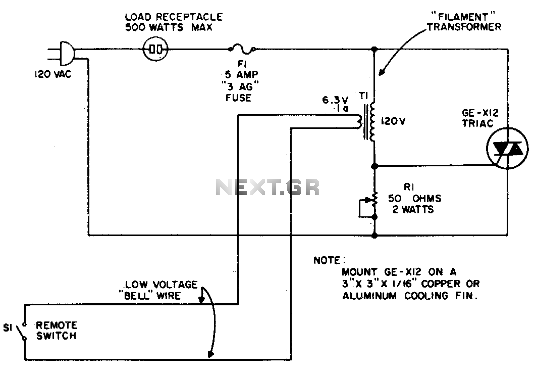
The circuit utilizes the primary current of a small 6-volt filament transformer to control a triac and activate the load. When switch S1 in the 6-volt secondary of the transformer is open, a small "magnetizing" current flows through the...