
Motor Speed Control Using PWM
PWM operates by varying the width of the pulses in a signal while maintaining a constant frequency. This method allows for precise control of the average power delivered to an electrical device by adjusting the duty cycle, which is the ratio of the "on" time to the total cycle time. For instance, a 50% duty cycle means the signal is on half of the time and off the other half, resulting in an average power output that is half of the maximum.
In practical applications, PWM is widely used in motor speed control, dimming of lights, and in various power supply circuits. The implementation of PWM in motor control enables smooth acceleration and deceleration, reduces mechanical wear, and enhances energy efficiency. The use of high-frequency PWM signals minimizes audible noise in motors, as the switching frequency is typically above the audible range.
To design a PWM circuit for motor control, a microcontroller or a dedicated PWM controller can be employed. The microcontroller generates the PWM signal based on the desired speed input, which can be adjusted via a potentiometer or a digital interface. The PWM signal is then fed into a power stage, typically comprising a MOSFET or an IGBT, which acts as a switch that controls the motor's power supply.
The circuit should include protective components such as diodes to prevent back EMF from damaging the switching elements, as well as capacitors to filter voltage spikes. Feedback mechanisms, such as tachometers or encoders, can be integrated to provide real-time speed data, allowing for closed-loop control and further refinement of the PWM signal based on the motor's performance.
Overall, PWM stands as a versatile and efficient method for power regulation in various electronic applications, particularly in the control of electric motors.Pulse width modulation or familiarly known as PWM is used to control the delivered power to load without loosing the efficiency. The speed of an electric motor.. 🔗 External reference
Related Circuits
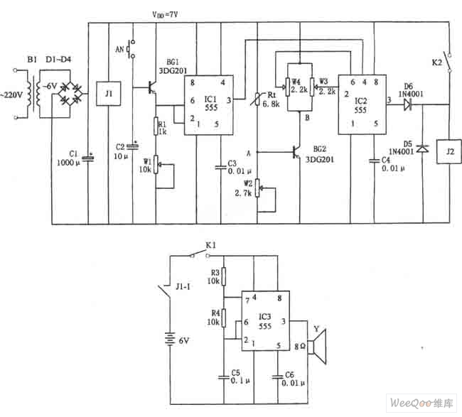
The figure illustrates the automatic watering control circuit for bean sprouts. The controller includes a step-down rectifier circuit, a power outage detection component (IC3), a timing control circuit (IC1), and a temperature control circuit (IC2). The step-down rectifier circuit...
Just point this small device at the TV and the remote gets jammed. The circuit is self-explanatory. 555 is wired as an astable multivibrator for a frequency of nearly 38 kHz. This is the frequency at which most of...
This beeper circuit utilizes two 555 integrated circuits (ICs) and can operate within a supply voltage range of 5 to 15V DC. It is suitable for applications requiring an alarm or beeping signal. The first IC (IC1) is configured...
The following diagram is for the main circuit of the motor driver. A testing version is shown near the end of this page. It is laid out differently and shows the SN7474 in logic block form and LEDs are...
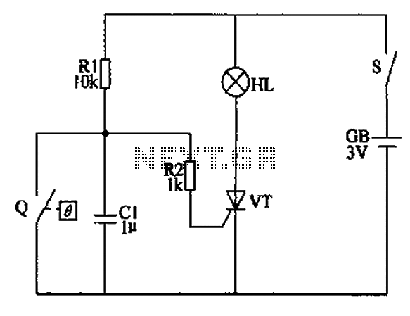
The automatic anti-frost crop controller circuit comprises an electric contact mercury thermometer (Q), a control circuit, ignition devices, and other components. The electric contact mercury thermometer features two platinum electrodes; one acts as a contact electrode inserted at the...
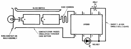
The schematic presented below illustrates the Flashlight Finder circuit diagram utilizing the LM3909, a monolithic oscillator specifically designed for flashing Light Emitting Diodes (LEDs). The Flashlight Finder circuit employs the LM3909 integrated circuit, which is capable of generating a series...