
light sensor circuit using pic16c63

This light sensor circuit is designed to interface a photosensor with electronic components, effectively bridging the gap between optical signals and electronic processing. The core of the circuit comprises an operational amplifier (op-amp) and the PIC16C63 microcontroller, which collectively manage the control of the photosensor. The circuit is not optimized for high-precision applications; however, it is well-suited for positional photo sensing applications where stability issues associated with amplifiers are minimized.
The architecture allows for the integration of a programmable gain amplifier (PGA) with multiple channels—specifically two, six, or eight channels. This design flexibility enables the incorporation of additional sensors or arrays of photosensors without the need for extra signal conditioning hardware or increased consumption of I/O pins on the PIC microcontroller. Such a setup is advantageous in complex systems where multiple inputs are required, as it maintains efficiency in both hardware and software.
The circuit utilizes a multiplexer paired with a high-speed conversion response from the PGA to ensure that the photosensor input signal can be sampled and converted to the digital domain swiftly. The use of the Serial Peripheral Interface (SPI) allows seamless communication between the PIC16C63 microcontroller and the PGA, facilitating rapid channel switching. This feature is critical in applications where real-time data acquisition is necessary.
The PGA can be configured for different settings with the photosensor, accommodating a range of signal responses from direct current (DC) to frequencies of approximately 100 kHz. This versatility makes the circuit suitable for various applications in light sensing and monitoring, allowing for effective signal processing and data interpretation in electronic systems.This light sensor circuit that is photos sensor is the gap between light and electronics. This circuit is built by op amp and microcontroller PIC16C63 for control the sensor. This circuit is not precision application, but they can be effectively used in position photo sensing applications minus the headaches of amplifier stability. This is the fig ure of the circuit. When the two, six or eight channel PGA is used in this system, the other channels can be used for other sensors or an array of photo sensors without an increase in signal conditioning hardware or PIC micro ® microcontroller I/O pin consumption. The multiplexer and high-speed conversion response of the PGA / Analog-to-Digital (A/D) conversion allows the photo sensor input signal to be sampled and quickly converted to the digital domain.
Switching from channel to channel is then easier with the Serial Peripheral Interface (SPI) from the PIC16C63 microcontroller to the PGA. The PGA can be configured with a photo sensor in two different settings. These circuits are appropriate for signal responses from DC to ~100 KHz. [Schematic circuit source: Microchip Technology, Inc] 🔗 External reference
Related Circuits
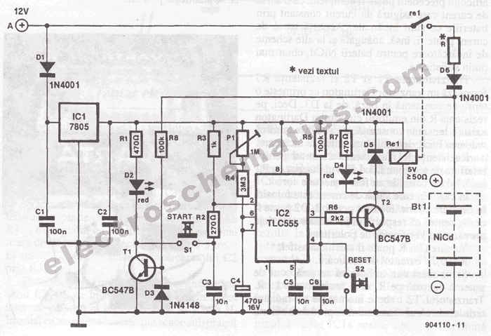
The portable battery charger has been designed to enable the charging of NiCd batteries outdoors using a 12 V vehicle battery. The portable battery charger is engineered to facilitate the charging of Nickel-Cadmium (NiCd) batteries in outdoor environments, leveraging the...
The circuit consists of a lag comparator with amplifier A1 and an inverting integrator A2. The charging and discharging time constant is determined by the integral resistors (R1 + RP1) and the capacitor C1. Diodes VD1 to VD5 form...
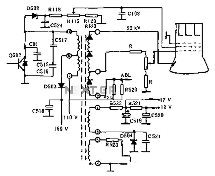
The circuit diagram of the Swallow CS37-2 type color TV illustrates the feeding tube configuration. The filament voltage is supplied by the line flyback transformer, with a current-limiting resistor R523. The accelerating voltage is managed by D502, which rectifies...
Incorporate resistors in a parallel configuration to enhance audio input. To control the volume for each input channel, integrate a linear trimmer or potentiometer with the following configuration: pin 1 connects to ground, pin 2 serves as the output,...
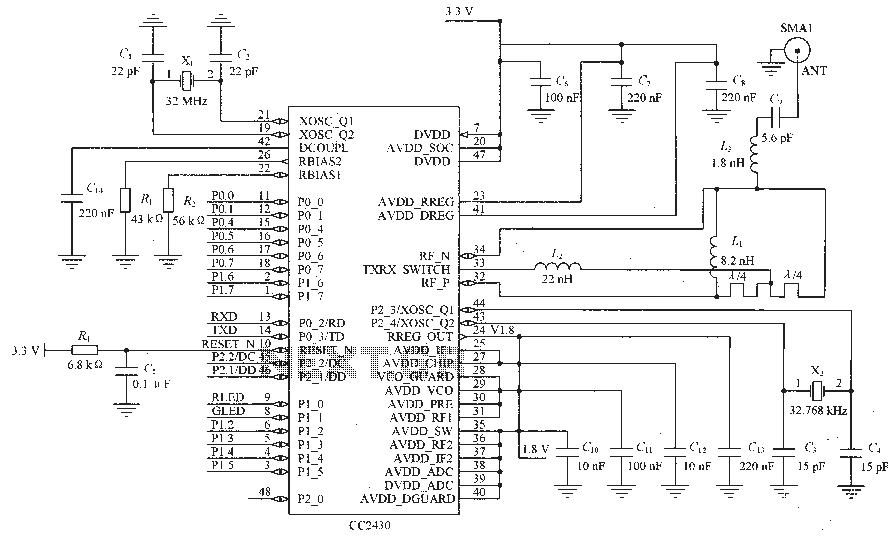
Figure C1 and C2 depict a 22 pF capacitor connected to a 32 MHz crystal oscillator circuit, which utilizes a quartz crystal for standard operation. Capacitors C3 and C4, each rated at 15 pF, are connected to a 32.768...
The WPG DM8168 DaVinci high-definition video System on Chip (SoC) offers multiple DVR/NVR surveillance solutions, utilizing the MT9M033 image sensor as a key component in safety monitoring systems. This solution is complemented by Conexant's line of multi-channel video surveillance...