
Electric fence control circuit
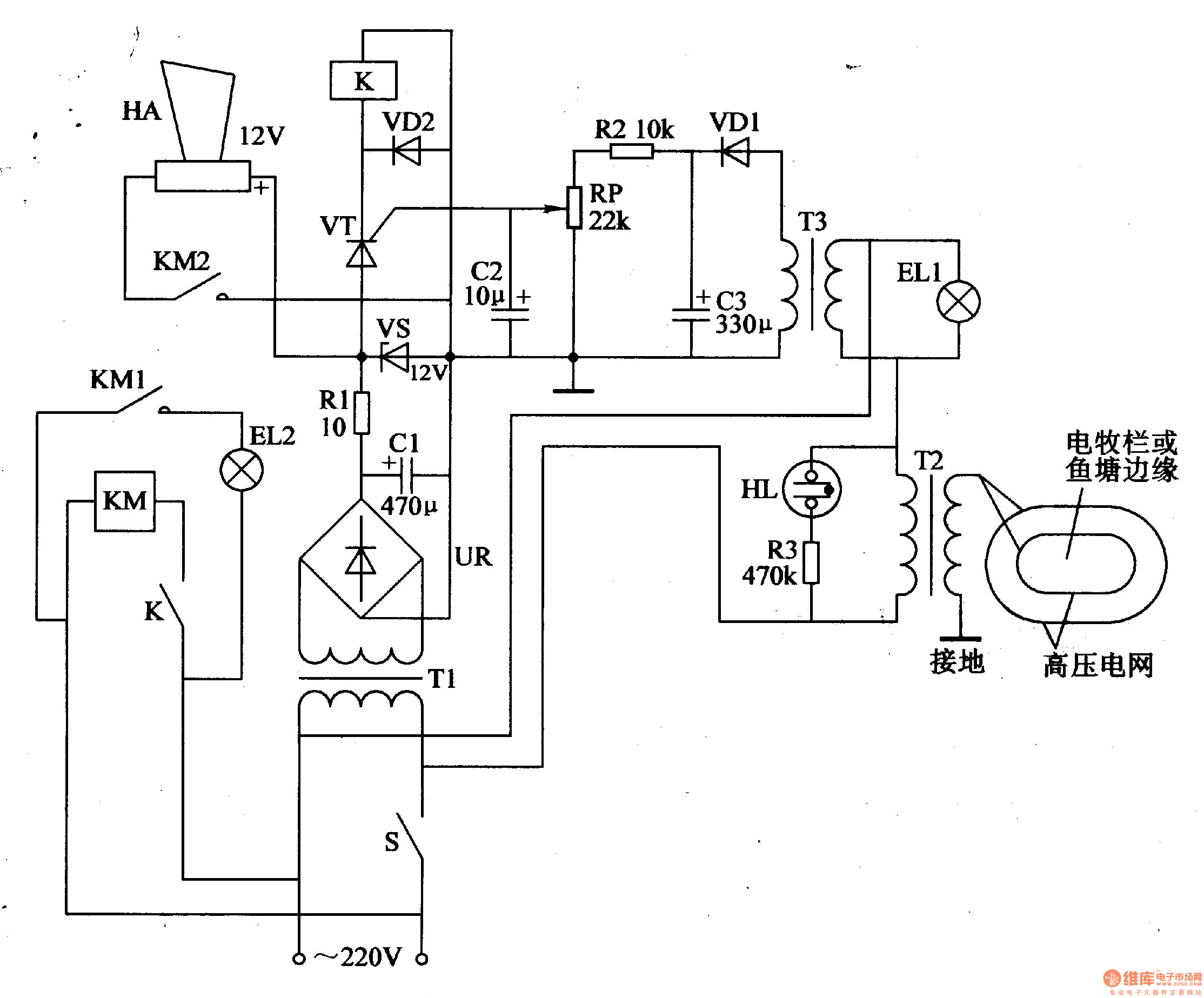
The electric fence control circuit operates by converting mains voltage into a high voltage pulse that can deter intruders. The power supply circuit begins with the power switch (S), which allows the user to turn the system on or off. When the switch is engaged, the power transformer (T1) steps down the mains voltage to a lower AC voltage suitable for rectification.
The bridge rectifier (UR) consists of four diodes arranged to convert the AC voltage output from the transformer into a pulsating DC voltage. This pulsating DC is then smoothed out using the filter capacitor (C1), which reduces voltage fluctuations and provides a more stable DC output. The current limiting resistor (R1) is crucial for protecting the circuit by limiting the amount of current flowing to the subsequent components. The voltage regulator diode (VS) ensures that the output voltage remains constant, providing a reliable power source for the high voltage circuit.
The high voltage circuit generates the necessary voltage to create an electric shock when an intruder comes into contact with the fence. This circuit is designed to produce high-voltage pulses at regular intervals to ensure the fence remains an effective deterrent.
The sound and light alarm circuit is triggered when the electric fence is breached. This circuit typically includes a buzzer or speaker for sound alerts and an LED or other light source for visual alerts. The output from the high voltage circuit can be linked to this alarm system, ensuring that any tampering with the fence is immediately signaled to the property owner.
Together, these components form a comprehensive electric fence control circuit that provides security through deterrence, enabling effective monitoring and alarming in case of unauthorized access.The electric fence control circuit is composed of the power supply circuit, high voltage circuit and sound and light alarm circuit, and it is shown in Figure 4-26. Power supply circuit is composed of the power switch S, the power transformer Tl, bridge rectifier UR, filter capacitor Cl, current limiting resistor Rl and the voltage regulator diode VS.
The h.. 🔗 External reference
Related Circuits
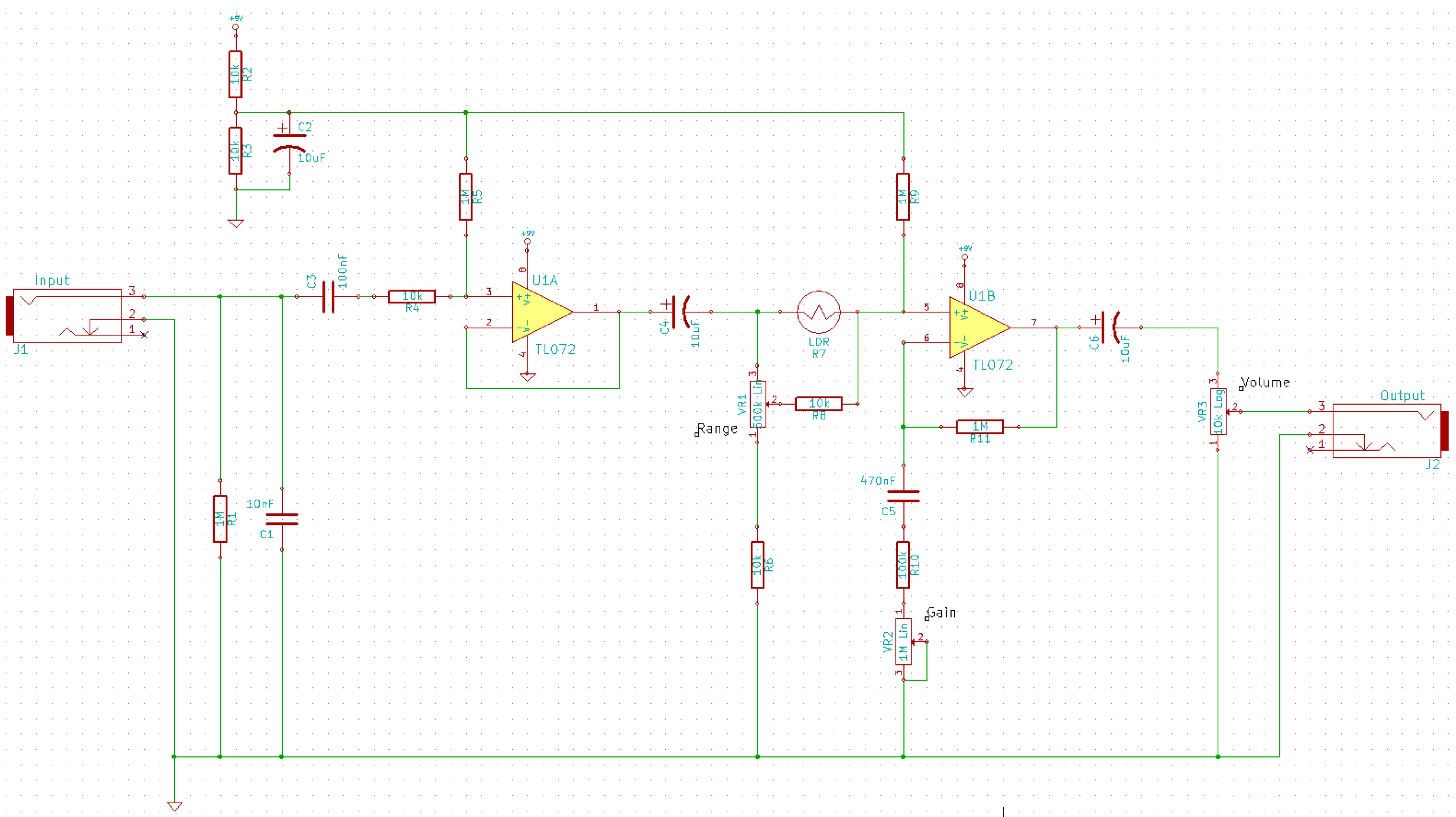
This is a simplified schematic for the Solar Lifeforce. The design eliminates the expression/CV output features and the toggle for the buffer, making it a straightforward circuit. It may benefit from adding small capacitors between R5 and ground, as...
This is a digital dice circuit that uses the PIC16C84. The digital dice circuit utilizing the PIC16C84 microcontroller is designed to simulate the random rolling of a standard six-sided die. The circuit operates by generating a random number between 1...
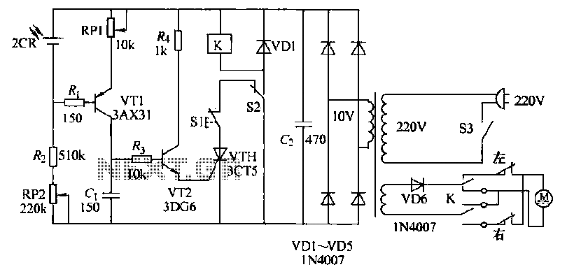
The circuit operates as follows: each morning, light enters the silicon photocell, generating a force that causes transistor VT1 to conduct. As a result, capacitor C charges, leading to an increase in voltage. This rising voltage causes the emitter...
This is a transistor tester integrated into a circuit or printed circuit board (PCB). It is utilized when a project does not function correctly, allowing for the testing of electronic components. The transistor tester is a crucial tool in electronic...

This circuit was designed to obtain a valve-like distorted sound from an electric guitar or other musical instrument. For this purpose a very high gain, three-FET amplifier circuit, was used. The output square wave shows marked rounded corners, typical...
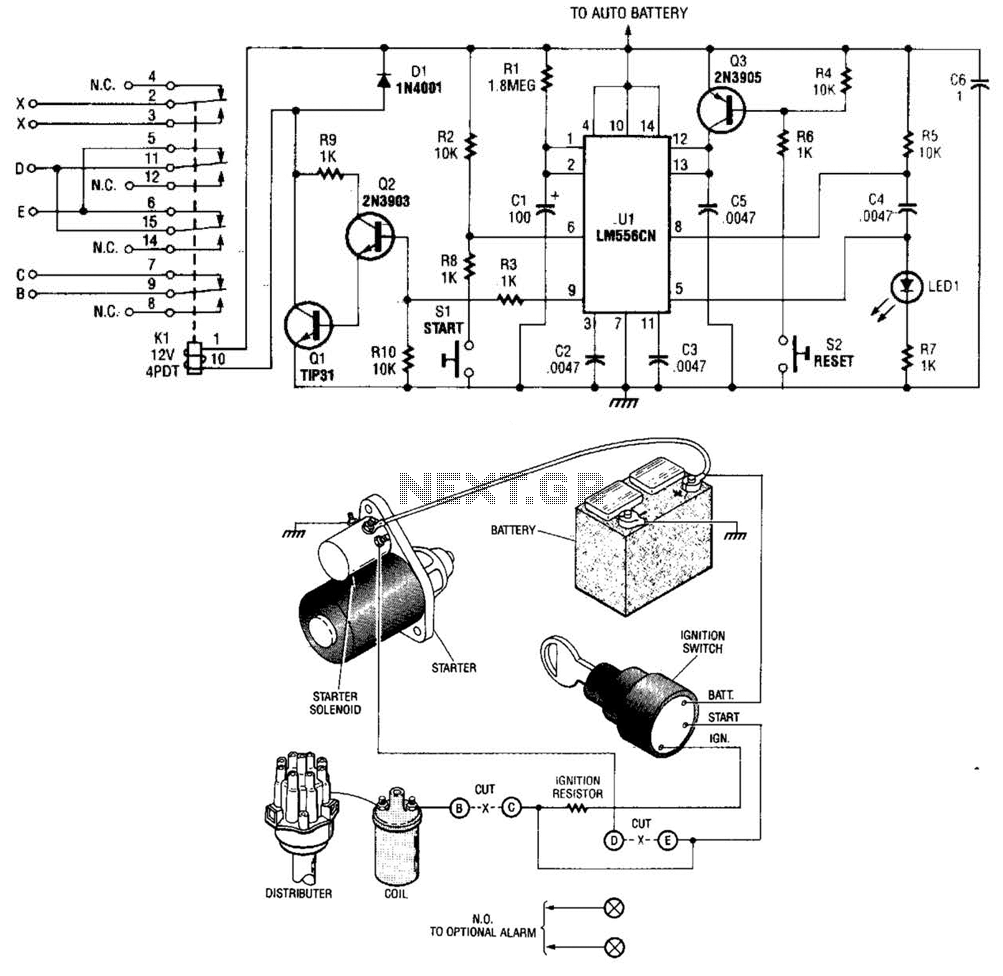
The automobile delayed kill switch operates on a straightforward principle. Upon exiting the vehicle, a hidden pushbutton switch is activated. Although no immediate effect is visible, after a preset duration, a relay engages and locks in place. This action...