
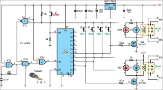
Fuzz-box circuit

The described circuit utilizes a high-gain three-FET (Field Effect Transistor) amplifier configuration to achieve a distinctive valve-like distortion effect, which is particularly favored in electric guitar applications. The design leverages the nonlinear characteristics of FETs to create a warm, rounded distortion that emulates the sound produced by vacuum tubes when pushed into saturation.
The input stage of the circuit is designed to accept low-level signals, with an input sensitivity specification of 30mV RMS. This allows for compatibility with a variety of musical instruments, ensuring that even weak signals can be effectively amplified. The three FETs are arranged in a manner that maximizes gain while maintaining stability and minimizing distortion at lower signal levels.
The output of the amplifier is characterized by a square wave with a peak-to-peak voltage of 6V, which indicates a robust output signal capable of driving further audio processing equipment or directly interfacing with a speaker system. The rounded corners of the output waveform are indicative of the soft clipping behavior typical in tube amplifiers, contributing to the overall warm sound profile that many musicians seek.
The circuit is designed to operate with a total current draw of approximately 1mA, making it energy-efficient and suitable for battery-powered applications. The setup process involves connecting a 1KHz sine wave generator to the input jack (J1) and monitoring the output with an oscilloscope connected to the output jack (J2). This allows for real-time analysis of the waveform characteristics and ensures that the circuit functions as intended.
Overall, this circuit represents a practical solution for musicians looking to replicate the tonal qualities of tube amplifiers in a solid-state format, offering a blend of high gain and pleasing distortion characteristics.This circuit was designed to obtain a valve-like distorted sound from an electric guitar or other musical instrument. For this purpose a very high gain, three-FET amplifier circuit, was used. The output square wave shows marked rounded corners, typical of valve-circuits when driven into saturation.
Technical data: Input sensitivity: 30mV RMS. Output square wave: 6V peak-to-peak max. Total current drawing: about 1mA. Circuit set-up using oscilloscope and sine wave generator: Connect a 1KHz sine wave generator to J1 and the oscilloscope to J2. 🔗 External reference
Related Circuits
Using high-beam headlights while driving on the highway can significantly enhance visibility; however, they may pose a blinding risk to other drivers. This straightforward circuit can be integrated into the headlight switch to enable automatic switching between high and...
This circuit is designed for use in a hi-fi showroom, allowing for the selection of different speakers to connect to a stereo amplifier for comparative listening. It can also serve similar applications where only one device from a set...
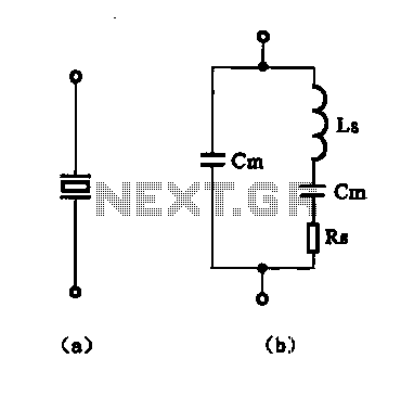
The crystal equivalent RLC circuit is illustrated. The RLC circuit can operate in either a series resonant or parallel resonant configuration. The crystal equivalent RLC circuit is a fundamental electronic circuit that models the behavior of a crystal oscillator. This...
A simple whole house FM transmitter circuit diagram and description. Operating power is a 1.5V battery of any type. This circuit is able to transmit at a distance of 30 meters. The whole house FM transmitter circuit operates on a...
The circuit presented is designed to prevent burning one's tongue by monitoring the temperature of coffee. It consists of a voltage regulator, a temperature-to-voltage converter, a comparator, and two LEDs. In general, the circuit operates as follows: if the...
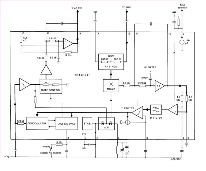
The TDA7021T integrated radio receiver circuit is designed for portable radios, both stereo and mono, where minimal peripheral components are essential for achieving small dimensions and low cost. It is fully compatible. The TDA7021T is a highly integrated radio receiver...
Warning: include(partials/cookie-banner.php): Failed to open stream: Permission denied in /var/www/html/nextgr/view-circuit.php on line 713
Warning: include(): Failed opening 'partials/cookie-banner.php' for inclusion (include_path='.:/usr/share/php') in /var/www/html/nextgr/view-circuit.php on line 713