
Solar Lifeforce LDR volume pedal circuit
The Solar Lifeforce circuit is designed to operate with a simple yet effective architecture, primarily focusing on the interaction between the LDR and the op-amp configuration. The LDR acts as a variable resistor that alters the circuit's resistance based on light exposure, which is critical for the intended volume control functionality. The use of a TL072 op-amp is advantageous due to its dual-channel capability, allowing for a compact design while maintaining performance integrity.
The reference voltage established by R2, R3, and C1 is crucial for the op-amp's operation, as it sets the baseline level for signal processing. The buffer stage ensures that the signal integrity is maintained before it is processed by the gain stage. The gain configuration, determined by R9 and R10, allows for precise control over the amplification factor, which is essential for compensating for variations in ambient light conditions. The attenuation provided by VR2 allows for user-friendly adjustments to output volume, catering to different performance environments.
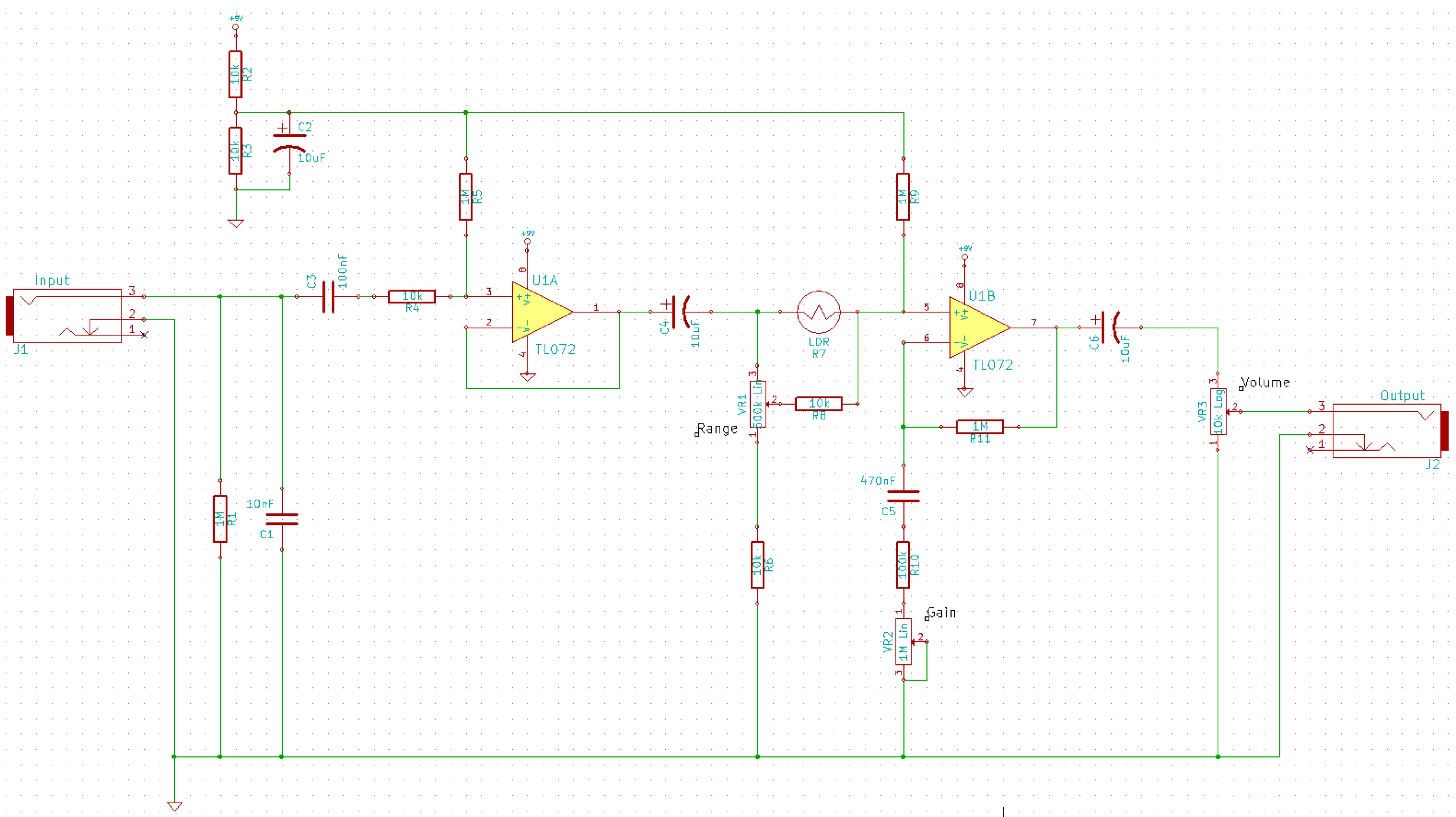
It is advisable to consider additional protective features, such as reverse polarity protection, particularly when deploying the circuit in varied settings. The inclusion of a capacitor like C4 ensures that any DC offsets are blocked, protecting downstream audio equipment. The overall design emphasizes flexibility and adaptability, making it suitable for musicians who require dynamic control over their sound in different lighting conditions. Proper mounting of the LDR and careful attention to light exposure will further enhance the circuit's performance and reliability.Here is a simplified schematic for the Solar Lifeforce. Basically I have removed the expression/CV out stuff, removed the toggle for the buffer so the buffer is always on, and made it as simple as possible. It could maybe do with some small value caps between both R5 and ground and R9 and ground, but they aren`t essential.
The LDR is a pretty unreliable thing for any consistent readings so maybe buy a bunch and try them out until you find one that suits you, I have tried the circuit with ones of varying specs and they all have behaved OK. The best I found was on doctor tweeks website which can be found here. It has a dark resistance of 20M which is plenty, 10 lux (room` light) resistance is between 50k-100k and it has a rise time of 20ms and a decay time of 30ms.
Before I go into the circuit I will warn you LDR`s aren`t perfect for cutting volume alone as they roll off treble, so your tone will be altered. This isn`t a problem so much when you are playing in really well-lit conditions but it does become noticeable when you are in stage type conditions.
Of course this may be what you want, but if you are after a transparent` volume cut a LDR is not the way to go. Anyway, here`s the circuit. I havent included the LED/switch wiring etc in this one, and I haven`t put in reverse polarity protection.
It is up to you if you think it is needed. If you think it is you could just use a diode such as a 1N4001 in series with the 9v rail. R1 is a pull down resistor to help prevent popping when the circuit is bypassed/engaged. R2, R3 and C1 form the network which establishes the reference voltage for the op-amp. The first side of the op-amp acts as a buffer, and the second side acts as a gain allowing you to increase the volume to compensate for poor lighting conditions. VR1 controls the range of the LDR between being covered and uncovered and R5 sets the minimum for this.
R9 and R10 set the gain of the b side of the op-amp, which is around 5 (G = 1 + (R10/R9) = 5. 545), which is then attenuated by VR2 just before the output. C4 stops any DC leaking from the circuit into your amp. You could use a lot of different op-amps for this circuit. I used a TL072 because I like them, have a few kicking around and is a dual op-amp so takes up less room than two signals. They are also pretty cheap and quiet so are good for this kind of work. On the Barefoot which was really the predecessor to the Solar Lifeforce I used DPDT toggle switch to change between if the signal kills when the LDR is covered or is restored there, you could probably mod this circuit to include it.
You could also use a DPDT toggle to cut the buffer out of the circuit if you wanted too easily enough. I wired the original so the buffer was independent of the pedals bypass, so the signal hit the buffer, then the bypass, then the rest of the circuit, but you could wire it after the bypass so that you have a switchable buffer aswell.
Just to clarify on this diagram the buffer is always in the circuit. R1=1M VR1=500k Lin VR2=10k Log. I found the best way of mounting those odd shaped LDR`s that are specified as 5mm diameter but aren`t actually round is to use a 5mm bezel mount. And be sure no light can get to it from inside the enclosure from the LED! 🔗 External reference
Related Circuits
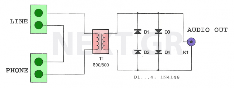
This circuit is designed to record telephone conversations on a landline telephone. It requires a small circuit and a computer subscription. Recording conversations is useful for recalling important discussions. Previously, this was accomplished using a small tape recorder, where...
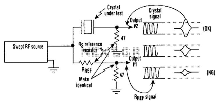
Occasionally, microprocessors and microcomputers may not be compatible with certain microprocessor crystals. Many data sheets for microprocessors specify maximum values for a crystal's equivalent series resistance (Rs), which may not be met by some crystals marketed for use with...
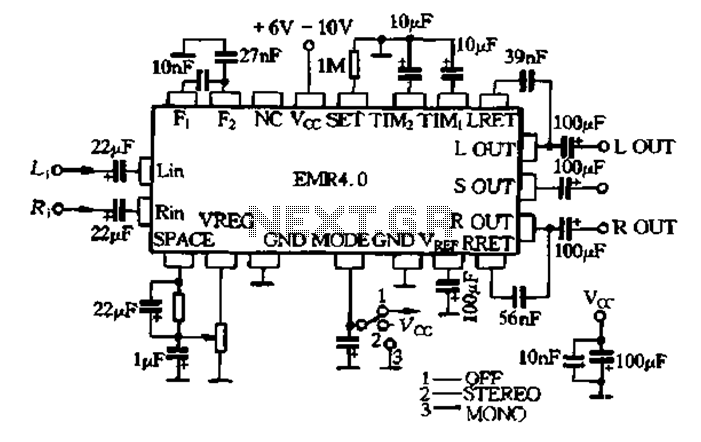
The EMR 4.0 operates with a single power supply ranging from 6V to 10V, with an optimal supply voltage of 9V. It requires effective power filtering to minimize noise, particularly when there is no signal input. The quiescent current...
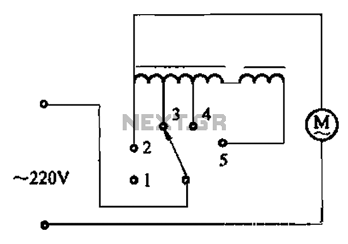
The circuit illustrated in Figure 3-2 features a loop reactor governor that incorporates a series reactor. The reactor can be constructed using a TV choke and is designed to be approximately 3mm in height. It utilizes a strength wire...
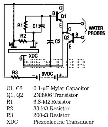
The moisture detector utilizes two transistors and a piezoelectric transducer to emit an alarm tone when water is detected. Transistor Q1 functions as a crystal-controlled oscillator, employing a portion of the piezoelectric transducer XDC, which consists of two piezoelectric...
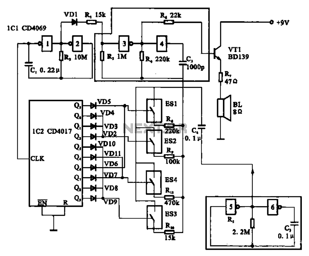
The circuit illustrated is an analog signal generator designed to produce a chirping sound, simulating birds singing. It employs six CD4069 inverters to create three oscillators, with two of them functioning as ultra-low frequency oscillators. The oscillation frequency is...
Warning: include(partials/cookie-banner.php): Failed to open stream: Permission denied in /var/www/html/nextgr/view-circuit.php on line 713
Warning: include(): Failed opening 'partials/cookie-banner.php' for inclusion (include_path='.:/usr/share/php') in /var/www/html/nextgr/view-circuit.php on line 713