
The designs and realizing of the electric current based on CAN bus line voltage transducer
The CAN bus system is characterized by its robustness in handling communication between multiple nodes, allowing for real-time data exchange in industrial automation applications. The architecture facilitates a decentralized control strategy, where each node can operate independently while still being part of a cohesive network. The use of twisted pair cables or fiber optics ensures reliable data transmission over varying distances, catering to the needs of complex industrial environments.
The microcontroller at the heart of the pickup node, the PIC18F258, is designed for high-performance applications and supports a variety of peripherals that enhance its functionality. Its compatibility with the CAN protocol allows for seamless integration with other devices in the network. The choice of the MAX1166 ADC ensures precise conversion of analog signals to digital format, which is critical for applications requiring high accuracy. This external ADC is capable of sampling at high speeds, thus facilitating the timely processing of data.
In summary, the intelligent instrument system based on CAN bus technology is a sophisticated solution for modern automation needs, offering flexibility, efficiency, and high accuracy in data collection and control. The architecture is designed to minimize network load while maximizing the reliability and speed of communication, making it suitable for a wide range of industrial applications.Field bus technology and intelligent instrument technology are automatic and controlling the trade to develop two major most quick technology at present. In the field bus technology, CAN bus line develops a kind of comparatively fast agreement standards, have already widely used in the automatic field.
What this text introduced is a kind of intell igence based on CAN bus line to pick up the system. Control device LAN ControllerAreaNetwork, CAN It was Germany Bosch Company at the beginning of the eighties of the 20th century for a kind of data communication that was developed of data interchange between numerous control and test instrument while solving Hyundai Motor Agreement. CAN bus line can support the serial communication network of distributed control or real time control effectively.
The communication medium can be paired line, coaxial and light-transmitting fibre. In order to should meet this control system requirement for centralized management as well as decentralized control, based on CAN bus line electric current, voltage pick up the system adopt the bus type network topology, low cost simple in construction. Its network makes up the way and is shown as in Fig. 1. Pick up the node and regard microcontroller as the core, is furnished with CAN communication interface in on-the-spot CAN intelligence, its main function is the real time data which are gathered every site plant, and hand in the data gathered to the monitor station through CAN bus line, for the monitor station to gather machine format essential information, thus carry on data analysis.
Monitor station PC Realize that observes and controls nodal communication with CAN intelligence through CAN2PC bus line adapting card in the slot. Unless in it is at system architecture, what mechanisms mains be adopted, can`t but last one main fact more than from network framework.
This way has lightened the load of the network to a certain extent. CAN intelligence is picked up the node has on-site data gathering, control and with CAN bus line communication function. This node regards Flash one-chip computer PIC18F258 with CAN control device of 8bit enhancement type with cost performance of great which Microchip Company produce as the core.
The compatible CAN performance test of this built-in CAN module in ISO requires, the maximum of bit rate is 1Mb/s, carry out CAN2. 0B protocol specification. The node of the transducer is mainly recuperated unit, A/D by the signal and gathered the module, control device of the one-chip computer and 4 parts of CAN bus line communication module to make up.
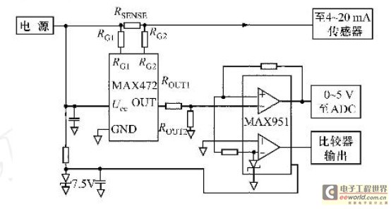
Intelligence this it picks up detection that nodes faces to be standard the intersection of electric current and signal that use industrially mainly in target 420mA/020mA/010mA With the voltage signal 05V/010V / 5V / 10V. First of all, electric current, voltage signal passing multiple-way switch choose the corresponding passway, enter signal, look after link, convert signal to ADC, at the same time can can accept voltage signal of input span, ADC of efficient use.
The signal after recuperating is changed through A/D, realize the digital conversion of the original analog signal. And store to his internal corresponding RAM district through mouth, I/O of one-chip computer, carry on the corresponding software and filter designing to the data.
As the upper computer gives an order, while requiring the loopback of lower-position unit to gather the data, the lower-position unit utilizes CAN bus interface unit to gather essential information such as the data to send to CAN bus line. Fig. 2 is the structural overall block diagram of system. Because this system measures the great of claimed accuracy to voltage, electric current, have not adopted PIC18F258 Built-in: 10bitADC during system design, but adopt the successive approximation type 16bit analog-digital converter MAX1166 that U.
S. A. Maxim Company produces as externally positione 🔗 External reference
Related Circuits
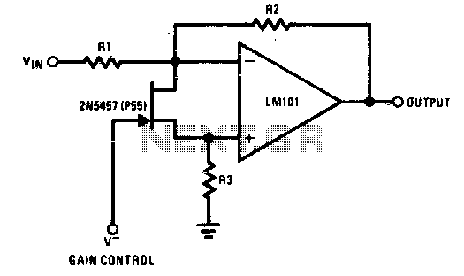
The 2N5457 functions as a voltage-variable resistor with a maximum RdS of 800 ohms. Given that the differential voltage on the LM101 is in the low millivolt range, the 2N5457 JFET exhibits linear resistance over several decades, offering excellent...
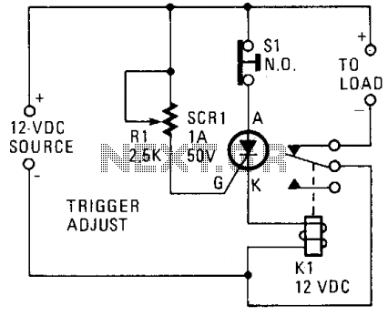
A silicon-controlled rectifier (SCR) is connected in parallel with the 12-V line and linked to a normally-closed 12-V relay, designated as K1. The gate circuit of the SCR is utilized to monitor the applied voltage. While the applied voltage...
This regulator circuit stabilizes the output voltage at 200V directly (without a transformer). Although the output voltage is high, this circuit only suffers a. The circuit in question is designed to maintain a stable output voltage of 200V without the...
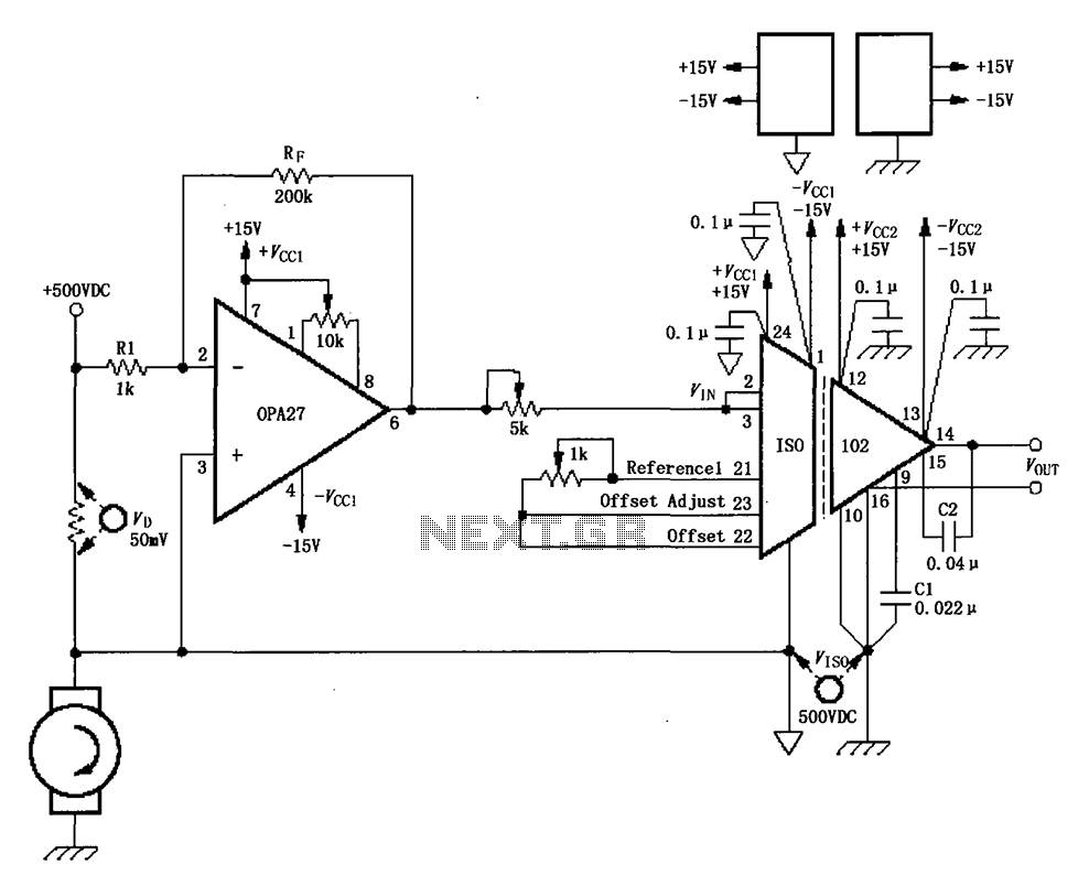
The circuit depicted in the figure consists of an ISO102 and OPA27 for measuring DC current at a voltage of +500V. It is configured between a +500V DC voltage source and a sampling resistor that is in series with...
This is a simple circuit of a Positive Voltage Doubler. This circuit utilizes the MAX1044/ICL7660. The Schottky diode was selected to reduce the voltage drop. The Positive Voltage Doubler circuit is designed to convert a lower input voltage into a...
Power the frequency counter and adjust the coarse (top pot) and fine (bottom pot) controls to display zero frequency. Turn the pots counter-clockwise to achieve a zero reading. Occasionally, the counter may show only squares without digits. If this...
Warning: include(partials/cookie-banner.php): Failed to open stream: Permission denied in /var/www/html/nextgr/view-circuit.php on line 713
Warning: include(): Failed opening 'partials/cookie-banner.php' for inclusion (include_path='.:/usr/share/php') in /var/www/html/nextgr/view-circuit.php on line 713