
Automatic Ni-Cd Battery ChargerCircuit
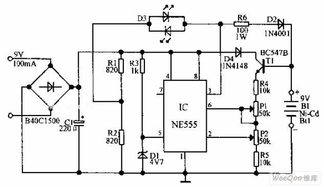
The automatic Ni-Cd battery charger circuit utilizes the NE555 timer IC in a comparator configuration to regulate the charging process. The Zener diode is employed to establish a stable reference voltage of 4.7V, which is crucial for determining the charging state of the battery. This reference voltage is connected to pin 6 of the NE555, while the voltage at pin 2 is monitored to assess the battery's charge level.
During operation, if the voltage at pin 6 surpasses 4.7V, the output at pin 3 transitions to a low state, signaling a reduction in the charging current to prevent overcharging. This feature is essential for maintaining the longevity and safety of the Ni-Cd batteries. On the other hand, if the voltage at pin 2 drops below half of the reference voltage (approximately 2.35V), the NE555 output at pin 3 will increase, allowing more current to flow into the battery for charging.
The circuit typically includes additional components such as resistors and capacitors to ensure stable operation and to filter out any noise that might affect the performance of the NE555 timer. A diode may also be included to prevent reverse current flow, protecting the circuit and the battery from damage.
In summary, this automatic Ni-Cd battery charger circuit effectively monitors and controls the charging process through the use of the NE555 timer IC, ensuring safe and efficient charging of the batteries while extending their operational life.Automatic Ni-Cd Battery Charger circuit is shown in the above picture. The internal comparator of NE555 is set as 4.7V by Zener diode. If the potential of pin 6 becomes higher than this value, the output of pin 3 become lower; if the potential of pin 2 is lower than half of the reference voltage, the output voltage becomes higher,. When the voltage of the.. 🔗 External reference
Related Circuits
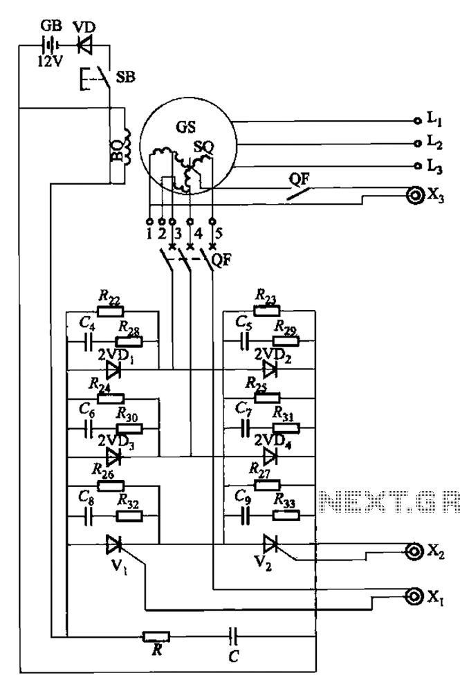
The setup is connected to separate stator windings of a harmonic generator, which leads to a thyristor rectifier supply for the third harmonic voltage, positioned after the motor field. The output voltage varies with changes in the winding harmonics...
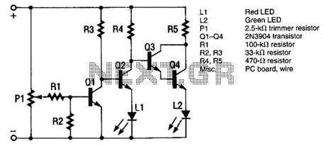
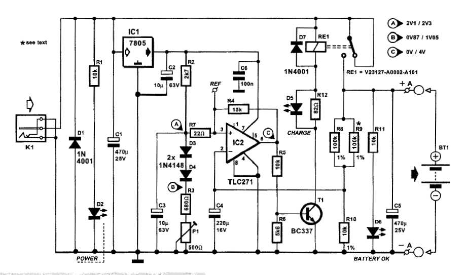
The monitor functions as a basic voltage comparator, utilizing a car battery as its power source. The input voltage to the comparator is adjusted using potentiometer PI. This adjustment ensures that the green LED L2 illuminates when the alternator...
This circuit can be utilized as a replacement for the single current limiting resistor commonly found in inexpensive battery chargers. The alternative presented here will eventually... This circuit serves as an improved solution for current limiting in battery chargers, particularly...
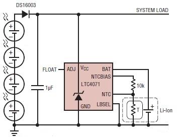
A simple solar-powered battery charger circuit can be designed using the LTC4071 Li-Ion/Polymer Shunt Battery Charger System with Low Battery Disconnect. When VCC reaches the programmed float voltage (4.1V with ADJ floating), the LTC4071 shunts excess current not used...
An automatic battery charger initiates the charging process when the battery voltage falls below a specified threshold and ceases charging once the voltage exceeds a predetermined maximum value. The setup is straightforward; simply connect two alligator clips to the...
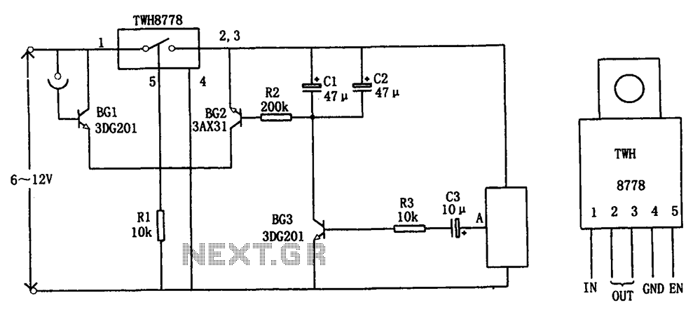
The circuit illustrated in FIG X pertains to automatic circuitry for US recorders. It primarily utilizes a new power switching device, TWH8778, which simplifies the design and eliminates the need for extensive debugging. The TWH8778's configuration and pin functions...
Warning: include(partials/cookie-banner.php): Failed to open stream: Permission denied in /var/www/html/nextgr/view-circuit.php on line 713
Warning: include(): Failed opening 'partials/cookie-banner.php' for inclusion (include_path='.:/usr/share/php') in /var/www/html/nextgr/view-circuit.php on line 713