
Electrometer amplifier with overload protection
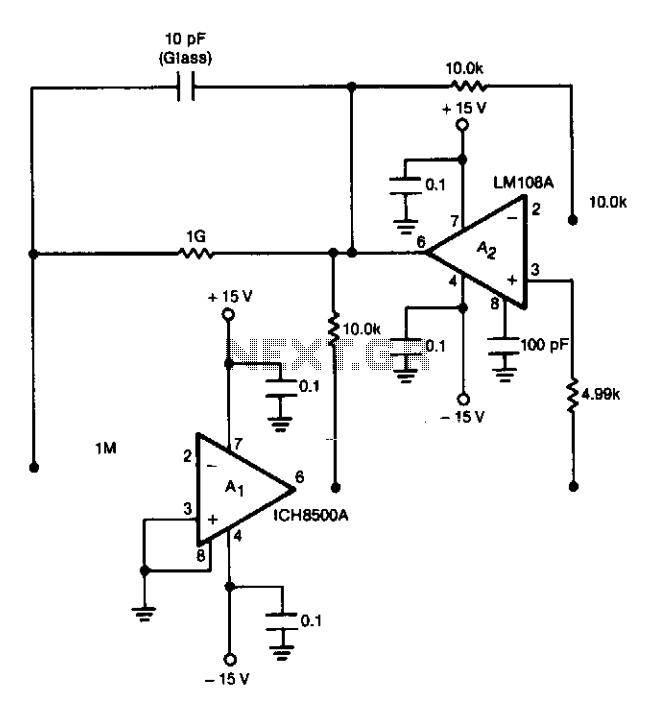
The preamplifier circuit is designed to ensure stability and accuracy in signal processing, particularly in applications where precision is paramount. The 2N5909 junction field-effect transistor serves as a protective element, preventing damage from high input signals while maintaining the integrity of the signal being amplified. The nulling circuit is critical for establishing a baseline output voltage, allowing for effective signal processing at low input current levels.
The standing current, which is a key parameter in the operation of the preamplifier, is set to a level that corresponds to the zero-signal condition, ensuring that any deviations from this state can be accurately measured and processed. The feedback resistor, valued at 109 ohms, is integral to creating the opposing current necessary to balance the standing current, thus enabling the preamplifier to operate effectively without distortion.
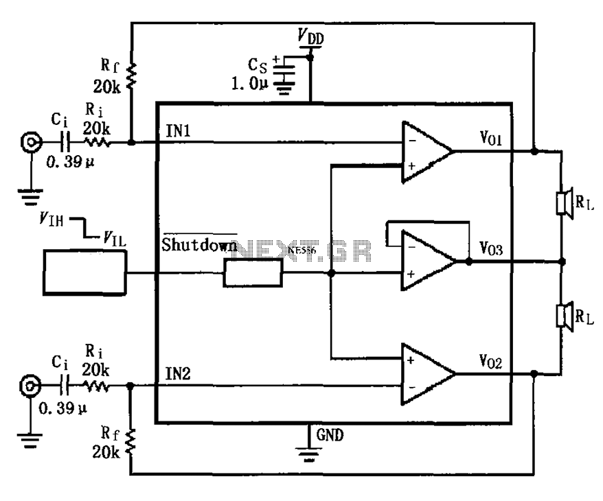
To accommodate varying signal levels, the preamplifier's output is directed to both low and high gain amplifier chains. This design allows for flexibility in signal amplification, catering to different application needs. The inclusion of a 1.5 Hz corner active filter in each amplifier chain is a strategic choice aimed at noise reduction. By filtering out unwanted high-frequency noise, the circuit enhances the signal-to-noise ratio, leading to clearer and more reliable output signals.
Overall, this preamplifier circuit is a robust solution for applications requiring precise signal amplification and noise management, making it suitable for a wide range of instrumentation tasks.The preamplifier is protected from excessive input signals of either polarity by the 2N5909 junction field-effect transistor. A nulling circuit makes it possible to set the preamplifier output voltage to zero at a fixed low level (up to + 10~8A) of the input current.
(This level is called the standing current and corresponds to the zero-signal level of the instrumentation.) The opposing (offset) current is generated in the 109 feedback resistor to buck the standing current. Different current ranges are reached by feeding the preamplifier output to low and high gain amplifier chains. To reduce noise, each chain includes a 1.5 Hz corner active filter. 🔗 External reference
Related Circuits

This stereo amplifier utilizes the NE5517/A and features an excellent tracking accuracy of 0.3 dB, which is typical. The offset can be adjusted using the potentiometer, Rp. For AC-coupled amplifiers, the potentiometer can be substituted with two 5.1 k...
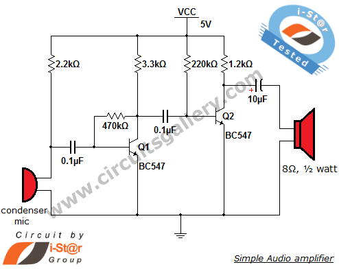
This circuit diagram is a simple and effective design for amplifying weak signals from a capacitive condenser microphone. It is suitable for sound sensing applications and various automatic robotic sensors. While a more complex audio amplifier circuit using the...
The LM317 integrated circuit (IC) is commonly recognized as an adjustable voltage regulator. However, it also has the capability to function as an audio amplifier, specifically in Class A configurations. The LM317 can be utilized in audio amplification applications due...
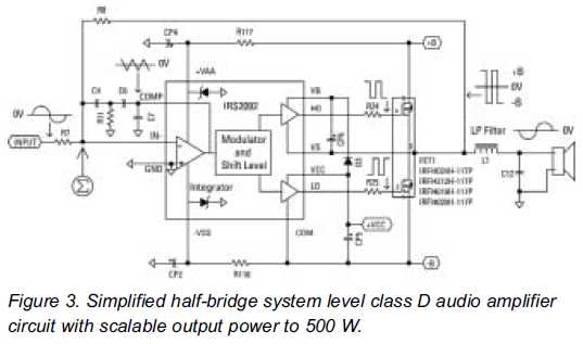
Class D audio amplifiers are now prepared to replace Class AB amplifiers. An integrated high-voltage audio driver simplifies the design and construction of high-power audio systems. Class D audio amplifiers, also known as switching amplifiers, utilize pulse-width modulation (PWM) to...
The LM4910 typical circuit is designed for a two-channel amplifier. The left and right channel audio signals are input to the LM4910 (in an MSOP/SO package) at pins 1 and 2. The output signals are delivered from pins 6,...
This circuit is a signal line so that you reinforce with a small speaker can control. The LM 386 is a number of versions available. LM 386N-1 can provide a power of 325 mW, the LM-386N 2500 mW, the...