
Electronic Canary

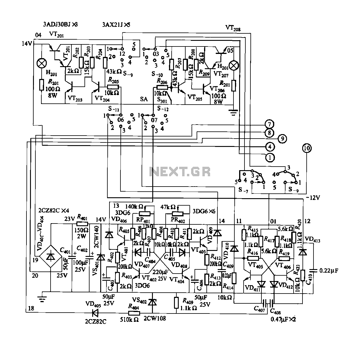
The modified Hartley oscillator circuit enhances the traditional design by integrating extra components that can improve performance characteristics such as stability, frequency response, and output signal quality. The core of the circuit remains the same, utilizing a pair of inductors and a capacitor to establish oscillation.
In this configuration, the small audio transformer serves a dual purpose. It not only provides impedance matching to optimize power transfer but also can be used to couple the output signal to subsequent stages in an audio application. The transformer’s primary and secondary windings can be connected in a way that influences the feedback and oscillation frequency, allowing for fine-tuning of the circuit's performance.
Additional components may include resistors and capacitors that can be strategically placed to filter noise, stabilize the oscillation frequency, and improve the overall linearity of the output signal. The inclusion of these components can also help mitigate issues such as distortion and unwanted harmonics, which are critical in audio applications.
Overall, this modified Hartley oscillator circuit represents an effective approach to generating audio frequencies with improved performance metrics, making it suitable for various applications in audio electronics, including signal generation and processing.This is a circuit which is a modification of Hartley oscillator with the addition of several components. This circuit uses a small audio transformer, type.. 🔗 External reference
Related Circuits
FGDF-3 is a three-phase low-temperature iron plating power commutation control switch and electronic circuit. The KGDF-3 serves as a low-temperature iron plating power supply device, incorporating the characteristics of a single-phase low-temperature iron plating power supply. This design facilitates...
A keyboard key functions by establishing an electrical contact between the surface of the keyboard and the underlying circuit when the keytop area is pressed. This mechanism was utilized by some home computers in the early 1980s and has...
The digital lock shown below uses 4 common logic ICs to allow controlling a relay by entering a 4 digit number on a keypad. The first 4 outputs from the CD4017 decade counter (pins 3,2,4,7) are gated together with...
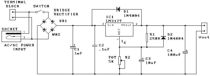
A potentiometer, designated as R2, can be utilized to adjust the desired output voltage. The kit is capable of accepting either AC or DC input through a socket or terminal block. It is advisable to incorporate protection diodes when...
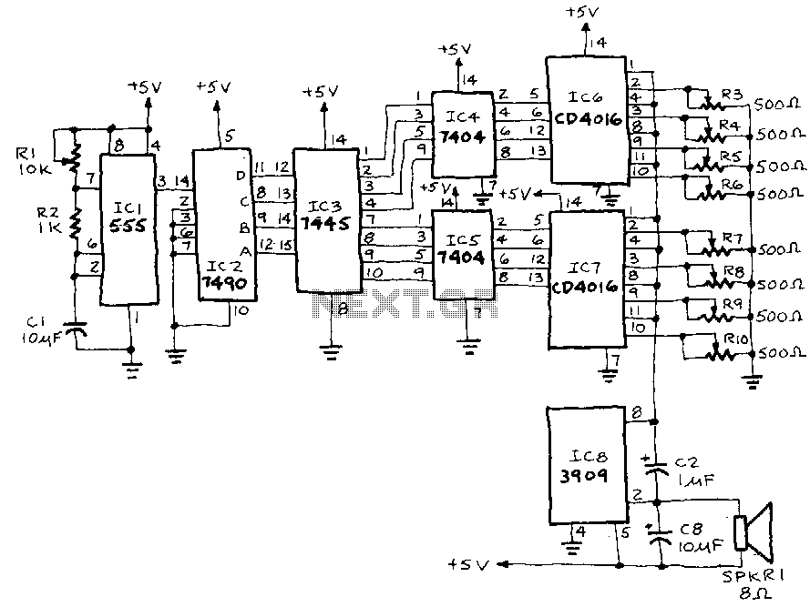
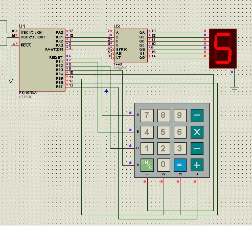
IC1, a 555 timer, is configured as an astable multivibrator to generate a signal that triggers IC2, a 7490 decade counter. This counter produces a BCD output that is connected to IC3, a 7445 BCD-to-decimal decoder/driver. The output from...
This laser is constructed on a polystyrene sheet. An aluminum foil layer acts as a ground plate (-), which is important for preionization. After that, the dielectric is placed on it, leaving 1 cm from each border of the...