
Electronic Canary Circuits
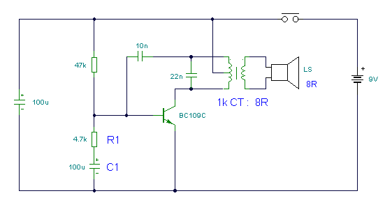
The modified Hartley oscillator circuit is designed to generate audio frequency signals characterized by a distinctive chirping sound. The core of the circuit is the audio transformer, LT700, which facilitates signal amplification and impedance matching. The center-tapped primary winding allows for a balanced operation, enhancing the oscillator's stability and efficiency. The impedance values indicate that the circuit is optimized for audio applications, typically operating within the range of 1 kHz.
The inclusion of R1 and C1 serves a dual purpose. R1 not only provides biasing for the transistor but also influences the charging and discharging time constants of the capacitor C1. The 100 µF capacitor plays a critical role in determining the oscillation frequency; as it charges through the 4.7 kΩ resistor, the voltage across it increases until it reaches a threshold that allows the transistor to conduct. When the transistor is cut off, the oscillation halts, and the capacitor discharges through the base-emitter junction, reinitiating the oscillation cycle.
The frequency of the chirp can be adjusted by varying the values of R1, C1, or the charging resistor, thus providing a means to tailor the output frequency for specific applications. The chirp's frequency is also influenced by the supply voltage, making the circuit adaptable to different power sources. The push-button switch serves as a control mechanism, allowing the user to initiate the charging of the capacitor; upon release, the rapid decay of oscillation leads to an increase in chirp frequency, creating a dynamic audio effect.
Overall, this modified Hartley oscillator circuit exemplifies a versatile design that can be utilized in various audio applications, including sound effects generation, alarm systems, and other creative electronic projects.This circuit is a modified Hartley oscillator with a couple of extra components included. The transformer is a small audio transformer, type LT700. The primary is center tapped with an impedance of 1Kohms at 1KHz. The secondary has an impedance of 8 ohms. The inclusion of R1 and C1 give this oscillator its characteristic "chirp". As the 100u capa citor charges via the 4. 7K resistor, R1 the bias for the transistor is cut off. This causes the oscillation to stop, the capacitor discharges through the base emitter circuit of the transistor and oscillations start again. Altering these components alters the frequency of the chirp. The chirp is also voltage dependent. When the push button switch is operated the 100u capacitor is charged. When its released, the oscillation decays and the chirp becomes faster. 🔗 External reference
Related Circuits
The controller for the Hybrid Power Plant (HPP) is represented in a block diagram format. It consists of 440 Wp photovoltaic modules, a 1 kW wind turbine, and a 5 kW diesel engine as a backup power source. The...
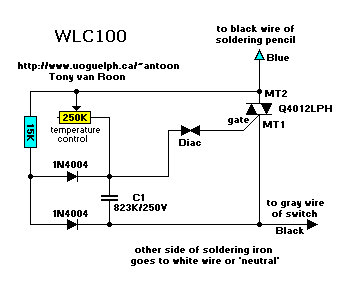
The following circuit illustrates the Weller WLC100 Electronic Soldering Station Circuit Diagram. This circuit utilizes the Q4012LPH Transistor. Features include safety measures, temperature control, and functionality as a soldering station that performs effectively for various applications. It is a...
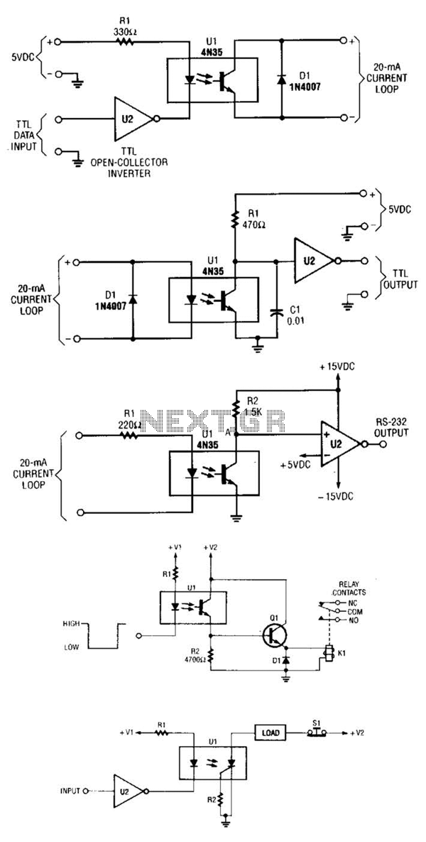
A circuit for isolating a variable resistor is presented. An optoisolator, which consists of an LED and a photo-conductive cell (or photoresistor), is utilized. The current flowing through the LED regulates its brightness, which subsequently dictates the resistance between...
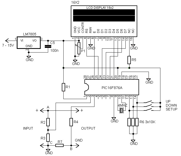
A voltmeter and ammeter using a PIC microcontroller can measure voltage and current simultaneously. This setup employs a PIC16F876A as the data processor for voltage and current measurements. An LCD display (16x2) is utilized to present the measured voltage...
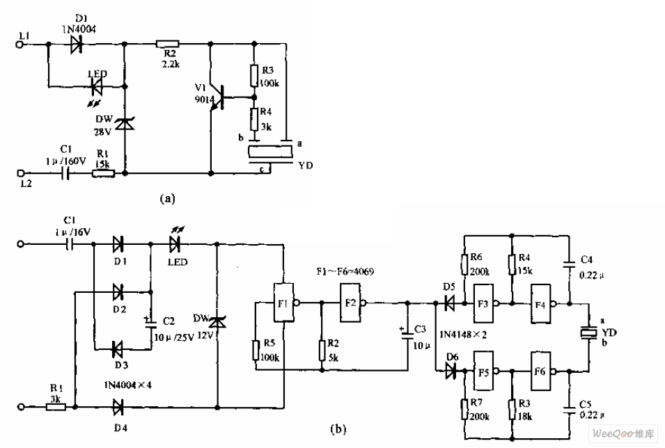
The telephone electronic ringer circuit is illustrated in the provided figure. It features an NPN transistor (either 9014 or 3DG12) as the primary component. The sound device, referred to as YD, functions as both a feedback device and is...
Utilize the program to customize your experience with the woven tules of roses on a single Adobe 3 Mac card. The system's reading portion remains idle while the controller operates, as illustrated in Figure 1. This setup includes the...