
Optoisolator And Optocoupler Interface circuits
The circuit design employs an optoisolator to achieve electrical isolation between different parts of the system while facilitating control of a variable resistor. The LED within the optoisolator is activated by a controlled current, which is influenced by the arrangement of the resistors R1 and R2. R1 functions as a current-limiting resistor to ensure that the LED operates within safe parameters, preventing damage due to excessive current flow. The potentiometer, which can vary its resistance, allows for fine-tuning of the LED brightness, thus adjusting the resistance encountered between terminals A and B.
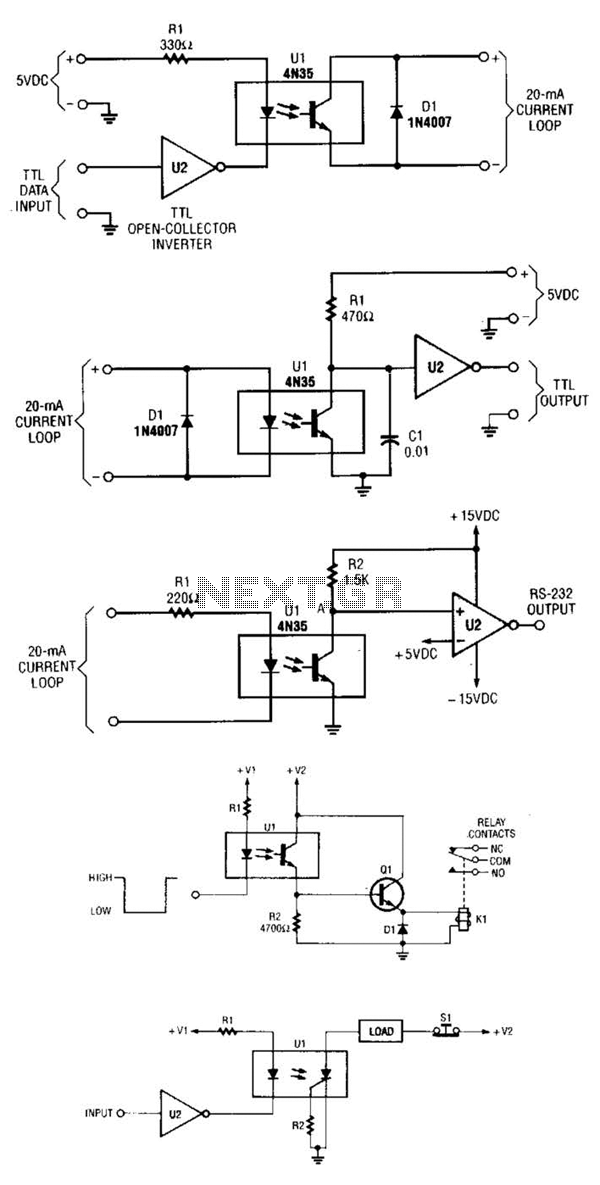
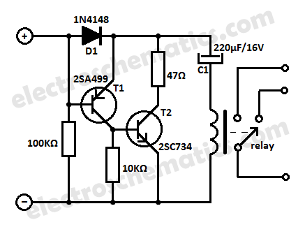
In scenarios where the load is too high for the optoisolator to handle directly, a relay can be integrated into the circuit. This relay acts as a switch that can be activated by the output of the optoisolator, allowing it to control larger currents or voltages safely. Schematic A demonstrates this configuration, highlighting the relay's role in managing heavy loads. Conversely, schematic B presents a simpler circuit that may suffice for lighter applications but lacks the capability for automatic shutoff, which could lead to potential hazards or inefficiencies in the system.
Overall, this circuit exemplifies the use of optoisolation in electronic designs to achieve safe and effective control over variable resistances, accommodating both light and heavy load scenarios through appropriate component selection and configuration. A circuit for isolating a variable resistor is shown. An optoisolator that has an LED arid a photo-conductive cell (or photoresistor) is used. The current through the LED controls its brightness, which in turn determines the resistance between terminals A and B. The LED current is set by the voltage of the dc power supply and the value of the two resistors (Rl and R2), The fixed resistor (Rl) is used to limit the current to a maximum of 20 mA (when the resistance of the potentiometer, is set to zero ohms), otherwise, the LED might burn out.
Very heavy hmdx, which can`t be powered directh by an optoisolator, might require the use of a rela as shown in A. You can sometimes i;el a way with using a circuit like that shown in B, hut it won`t turn itself off.
🔗 External reference
Related Circuits
When a new computer modem is introduced into a home, the demand on the phone line increases significantly. Internet users can consume phone time similarly to a chatty teenager. Additionally, computer modem users often prioritize their privacy; for instance,...
The ICs LM4651 and LM4652 are types of MOSFET integrated circuits and power amplifiers that include high-efficiency amplifiers, making them suitable for self-powered speakers, subwoofers, and high-quality car audio systems. The LM4651 is a fully integrated conventional pulse width...
The circuit features a serial coded modulated control signal that amplifies and transmits high-voltage isolation. It utilizes a 556 timer-based circuit along with resistors R1, R2, capacitors C1, and R3, R4, C2 to form two astable multivibrators. The circuit...
This low current relay circuit is designed for use in battery-operated electronic devices. Its operating current is in microamperes (µA). This is achieved by using a bistable relay and incorporating additional components to enable the relay to function like...
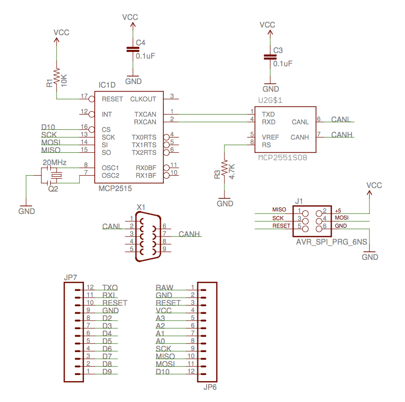
The implementation of the Controller Area Network (CAN) for aircraft applications is referred to as CAN-FIX, which is part of the MakerPlane Open Source Airplane project. This project aims to create an Arduino shield that facilitates communication over the...

The Switchgate is a simple dual gate circuit based on a 556 timer configured in monostable mode, featuring a trigger input that activates two switches. The outputs of the monostables are also available individually. Recent research has led to...