
pic volt and amere meter circuits
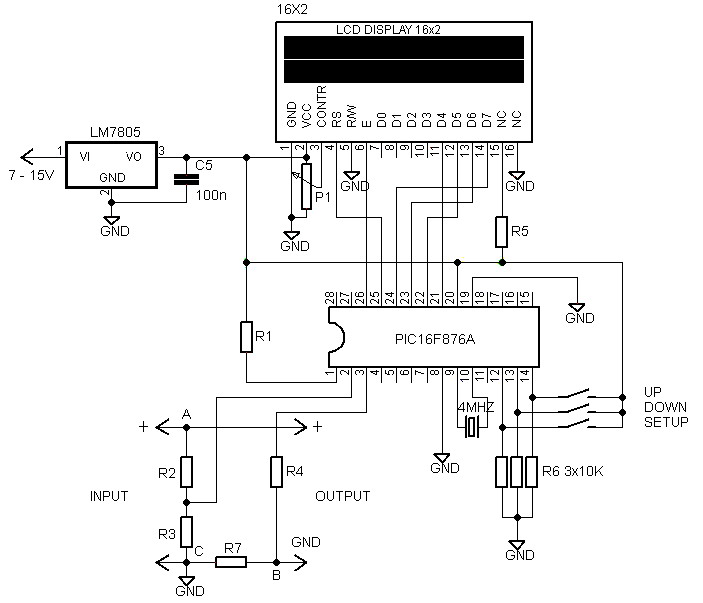
The voltmeter and ammeter circuit utilizing the PIC16F876A microcontroller is designed for simultaneous measurement of voltage and current. The microcontroller serves as the central processing unit, collecting data from the measurement sensors and processing it for display. The choice of the PIC16F876A is due to its capability to handle analog-to-digital conversion, making it suitable for accurate voltage and current readings.
The circuit architecture includes a voltage divider for voltage measurement and a shunt resistor for current measurement. The voltage divider scales down the input voltage to a range that can be safely read by the microcontroller's analog input pins. The shunt resistor, placed in series with the load, allows for current measurement by producing a voltage drop proportional to the current flowing through it. The microcontroller reads this voltage drop, applies Ohm's law, and calculates the current.
An LCD module, specifically a 16x2 display, is integrated into the circuit to provide a user-friendly interface for displaying the measured values. The display is connected to the microcontroller via an I2C or parallel interface, depending on the configuration chosen. This allows for real-time monitoring of voltage and current, enhancing usability in various applications.
Calibration is an essential aspect of this circuit, ensuring accurate measurements. The inclusion of three buttons facilitates user interaction for calibration purposes. These buttons can be programmed to set reference points or adjust the display for specific ranges, allowing for fine-tuning of the measurements based on user requirements.
The entire circuit operates on a 5V DC power supply, which is a common voltage level for microcontroller applications. This choice of power supply ensures that the circuit is compatible with a wide range of components and simplifies integration into existing systems.
Overall, the voltmeter and ammeter circuit with the PIC16F876A microcontroller offers a robust solution for simultaneous voltage and current measurement, with an emphasis on accuracy, ease of use, and flexibility through calibration options.Volt meter and ampere meter with PIC can be used to measure voltage and current at the same time. The series of volt meter and ampere meter with PIC uses a PIC16F876A as a data processor voltage and current are measured. This circuit uses a LCD viewer 16 G— 2, which is used for displaying data voltage and current measurements.
In the article voltmeter and ampere meter with PIC is to be discussed is limited to devices faucet only. For more details can be seen from the image sequence volt meter and ampere meter with PIC below. In the circuit volt meter and ampere meter with PIC above used 3 pieces of buttons for setting Calibration measurement data. The circuit is basically working with the source voltage 5VDC. 🔗 External reference
Related Circuits
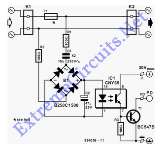
The detector is designed to sense and signal to another circuit when an appliance is connected to the mains voltage. For this purpose, an optocoupler, IC1, is utilized. The circuit employs an optocoupler (IC1) to provide electrical isolation between the...
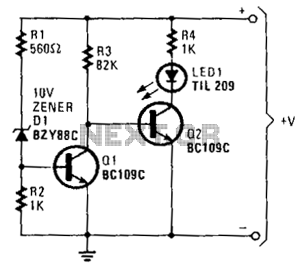
When the battery voltage exceeds approximately 11 V, current flows through resistors R1, D1, and R2. The voltage generated due to the current flowing through R2 is sufficient to turn on transistor Q1, effectively bringing its collector voltage near...
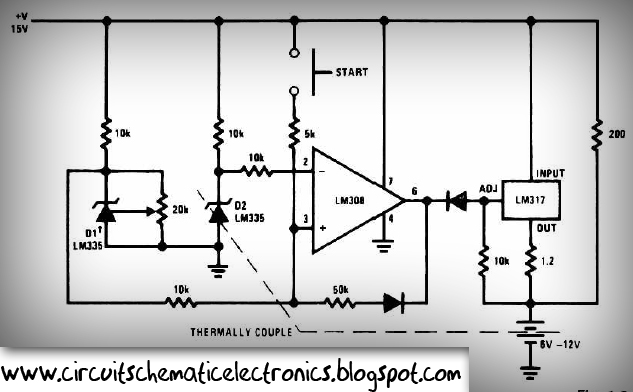
This circuit is designed for rapid battery charging. It is recommended for those who require a faster charger. The charger operates at a low temperature of 5 degrees Celsius. The input voltage is 15 volts DC, while the output...
The circuit diagram of the variable regulator utilizes the IC L200 as a regulator for both voltage and current. This integrated circuit is produced by the company. The L200 is a versatile adjustable voltage and current regulator that can deliver...
The battery voltage is 1V for a low-frequency amplifying circuit, which can operate with a power supply voltage ranging from 1V to 1.7V, making it suitable for use with small batteries. The circuit provides an output power of 80mW...
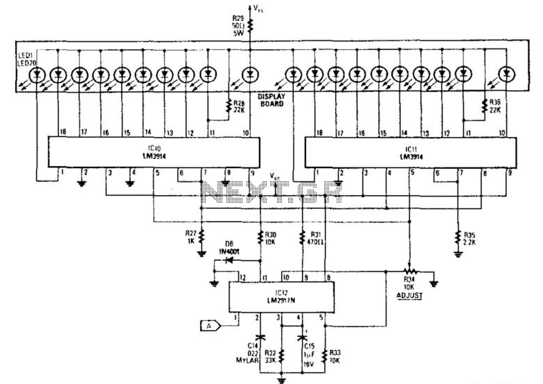
The analog display consists of a frequency/voltage converter (IC12) and bar-graph segment drivers IC10 and IC11. More: R34 is the calibration adjustment and is set so that an engine rpm of 5 000 to 7000 rpm lights the first...
Warning: include(partials/cookie-banner.php): Failed to open stream: Permission denied in /var/www/html/nextgr/view-circuit.php on line 713
Warning: include(): Failed opening 'partials/cookie-banner.php' for inclusion (include_path='.:/usr/share/php') in /var/www/html/nextgr/view-circuit.php on line 713