
Electronic coin tosser

The circuit operates using a simple mechanism that allows for a binary outcome, akin to a coin flip. When switch PB1 is pressed, it triggers a change in the output state of the circuit. This can be achieved using a flip-flop configuration, which is a common way to create a bistable multivibrator.
In a typical implementation, the circuit may utilize a 555 timer IC configured in a monostable mode or a D flip-flop. The pressing of PB1 would send a pulse to the clock input of the flip-flop, changing its state from low to high or vice versa.
The output can be represented through LEDs, where one LED lights up for heads and another for tails, providing a visual representation of the coin flip. Resistors may be included in series with the LEDs to limit current and prevent damage.
Power supply connections should be made to the circuit, typically utilizing a 5V or 9V source, depending on the components used. It is essential to ensure proper grounding to maintain circuit stability.
This simple circuit effectively demonstrates fundamental electronic principles while providing an engaging interaction through the physical act of pressing the switch.The circuit shown simulates the flipping of a coin by merely pushing switch PB1 An easy circuit. 🔗 External reference
Related Circuits
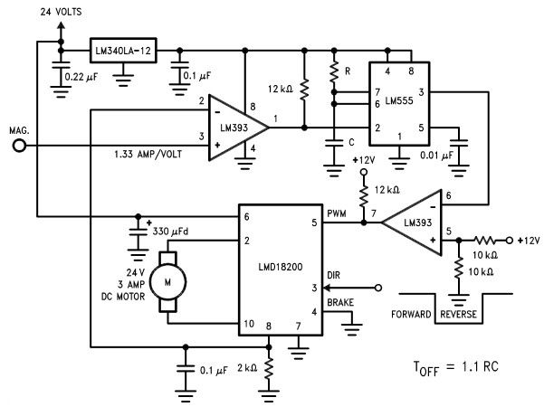
The LMD18200 3A H-Bridge, designed by National Semiconductors, can be used to create a simple motor controller electronic project suitable for motion control applications. This component is ideal for driving both DC and stepper motors, accommodating peak output currents...
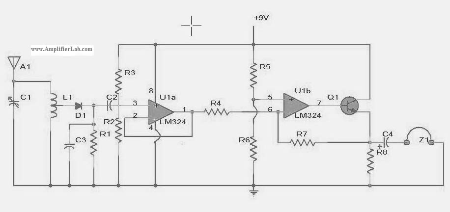
The following circuit illustrates a power amplifier electronic circuit, specifically a tube audio RF amplifier circuit diagram. This circuit is based on the LM324 integrated circuit. The power amplifier circuit utilizing the LM324 operational amplifier is designed to enhance audio...
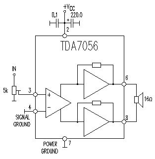
This TDA7056 power audio amplifier circuit diagram project is designed to deliver a maximum output power of 1 watt into an 8-ohm load when powered by a 6-volt supply, or a maximum output power of 3 watts into a...
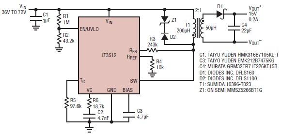
A straightforward dual 15-volt power supply electronic circuit can be created using the LT3512 switching regulator IC produced by Linear Technology. This basic 15-volt DC power supply operates with an input voltage range of 36 to 72 volts and...

The following diagram illustrates a straightforward electronic combination lock utilizing the IC LS7220. The component part list includes: C1 = 1µF 25V, C2 = 220µF 25V, R1 = 2.2K Ohm, Q1 = 2N3904 or 2N2222, D1 = 1N4148 or...

It is possible to simulate the balanced performance of a transformer electronically using a different amplifier. By adjusting the presets, the resistor ratio can be balanced to achieve the best Common Mode Rejection Ratio (CMRR). This method can yield...