
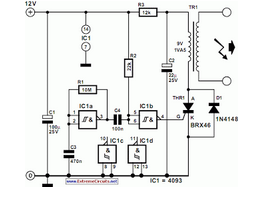
Simple Electronic Combination Lock
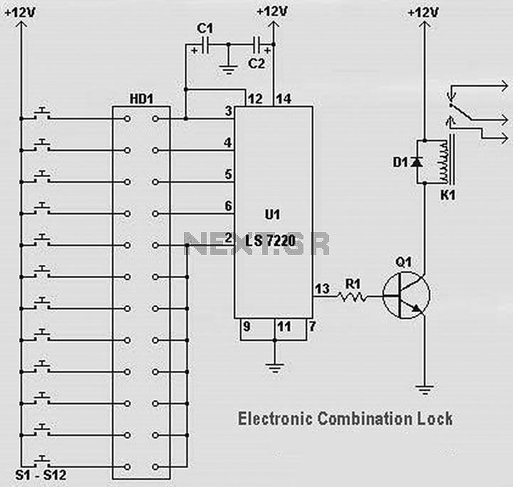
The electronic combination lock circuit primarily operates based on the LS7220 integrated circuit, which is designed for security applications requiring a coded input to unlock a mechanism. The LS7220 is a highly integrated device that provides the necessary logic to interpret the key sequence entered by the user.
The capacitor C1 (1µF, 25V) serves as a coupling capacitor, filtering out any noise from the power supply and ensuring stable operation of the IC. Capacitor C2 (220µF, 25V) acts as a decoupling capacitor, providing additional stability and energy storage for the circuit during operation.
Resistor R1 (2.2K Ohm) is used to limit the current flowing into the base of the transistor Q1 (either 2N3904 or 2N2222), which functions as a switch to control the relay K1. The choice of transistor allows for sufficient current amplification, enabling the relay to activate without overloading the IC.
Diode D1 (either 1N4148 or 1N4001-1N4007) is included to protect the circuit from back EMF generated when the relay coil is de-energized. This diode is connected in reverse bias across the relay coil terminals, ensuring that any voltage spike is safely redirected away from the sensitive components of the circuit.
The relay K1 (12V SPDT) serves as the actuating mechanism for the lock, allowing it to control a locking mechanism or other devices requiring a switchable action. The relay can be replaced with any appropriate alternative that meets the voltage and current specifications required by the application.
Overall, this combination lock circuit is designed for simplicity and effectiveness, making it suitable for various security applications where electronic access control is needed.The following diagram is a very easy and simple electronic combination lock based on IC LS7220. Component Part List: C1 = 1uF 25V C2 = 220uF 25V R1 = 2.2K Ohm Q1 = 2N3904 / 2N2222 D1 = 1N4148 / 1N4001-1N4007 K1 = 12V SPDT Relay / Any approp.. 🔗 External reference
Related Circuits
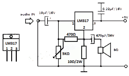
The LM317 integrated circuit (IC) is commonly recognized as a voltage regulator; however, it can also function as an audio amplifier. This low-power amplifier circuit designed with the LM317 provides a maximum output of approximately 1 watt. The LM317...
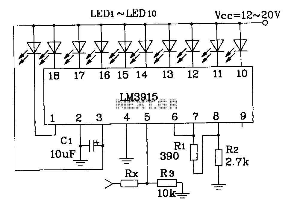
This document describes a simple LM3915 audio power meter circuit diagram. It notes that if the internal resistance of the speaker is 4 ohms, a resistor value of 10k ohms should be used for Rx. For an 8-ohm speaker,...
This RS232 power supply circuit diagram is a simple RS-232 line driver power supply that operates from an input voltage as low as 4.2V and delivers an output of ±12V at ±40 mA with an efficiency of better than...
The circuit is designed for conducting safe experiments with high-voltage pulses and operates similarly to an electrified fence generator. This circuit is engineered to generate high-voltage pulses suitable for educational purposes and experimentation. The design is inspired by electrified fence...
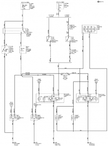
The connection and wiring between each part and component of the exterior lighting system of the vehicle includes elements such as the fusible link, junction block, tail light relay, cruise control, stop light switch, relay box, column switch, rear...
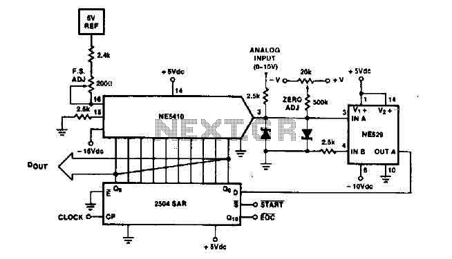
The time IO-bit conversion operates at 3.3 MHz with a clock signal. This converter utilizes a 2504 12-bit register in successive approximation mode, where the conversion signal for the short-cycle end is derived from the first bit utilized in...
Warning: include(partials/cookie-banner.php): Failed to open stream: Permission denied in /var/www/html/nextgr/view-circuit.php on line 713
Warning: include(): Failed opening 'partials/cookie-banner.php' for inclusion (include_path='.:/usr/share/php') in /var/www/html/nextgr/view-circuit.php on line 713