Electronic Communication Projects
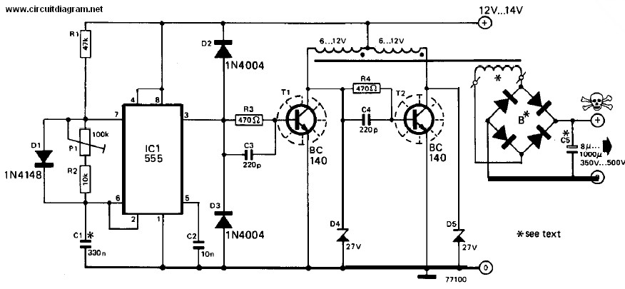
When the output of the multivibrator is low, Q1 (an NPN transistor) will be OFF and Q2 (a PNP transistor) will be ON. Consequently, the negative terminal of capacitor C3 will be connected to ground, allowing it to charge from the power supply through diode D1. In the second half of the cycle, when the output of the multivibrator is high, Q1 will be ON and Q2 will be OFF. Capacitor C4 will then be charged by the voltage from capacitor C3; however, its discharge through transistor Q1 is blocked by diode D1. The discharge of C4 through Q1 during the next half cycle (when the multivibrator output is low) is prevented by diode D2. The primary distinction between this circuit and the previous design, which operated from 12V DC to 240V AC, is the inclusion of a bridge rectifier at the output of the transformer. Additionally, several P-N diodes have been incorporated to prevent reverse current, thus safeguarding the circuit from accidental reverse currents. This circuit employs a 555 timer configured as an astable multivibrator. Diode D1 is utilized to ensure a 50% duty cycle for the multivibrator. For half of the time, Q1 remains OFF, driven by the direct voltage from the multivibrator. Specifically, Q1 will be OFF when the multivibrator output is low. In this state, Q2, which is connected to the collector of Q1, will be ON. During the subsequent period, Q1 will be ON while Q2 will be OFF. This design guarantees a constant voltage supply for the transistors. The circuit features an astable multivibrator using the 555 timer, where Q1 is OFF and Q2 is ON during low voltage output, and Q1 is ON and Q2 is OFF during high voltage output.
The described circuit operates as a controlled switching mechanism using a 555 timer configured in an astable mode, effectively generating a square wave output. The transistors Q1 and Q2 play critical roles in managing the charging and discharging cycles of capacitors C3 and C4, ensuring that each component operates within its specified voltage range. The use of diode D1 not only facilitates the charging of C3 but also establishes a duty cycle that is vital for the operation of the multivibrator, effectively allowing Q2 to conduct when Q1 is off, thus creating a complementary switching action.
The bridge rectifier at the transformer output serves to convert the AC voltage to DC, providing a stable voltage source to the circuit. This is essential for applications requiring consistent voltage levels, especially in power supply circuits. The inclusion of P-N diodes is a safety feature that protects the circuit from potential damage due to reverse polarity, ensuring longevity and reliability in various applications.
Overall, this circuit design is suitable for applications where a reliable switching mechanism is needed, such as in power supply regulation, signal modulation, or as part of a larger control system. The careful arrangement of components and the use of the 555 timer in astable mode facilitate a robust and efficient operation, making it a versatile solution in electronic circuit design.When the output of our multivibrator is low, Q1 (because it is NPN transistor) will be OFF and Q2(because it is PNP transistor) will be ON. So the negative terminal of capacitor C3 will be connected to ground. It will charge from the power supply and through the D1 diode. Second Half: When the o/p of multivibrator is High, Q1 will be ON and Q2 will be OFF. The C4 capacitor will be charged by the voltage of C3 capacitor. But its discharge through transistor Q1 is blocked by D1 diode. Discharge of C4 through Q1 during next half (that is low voltage of the multivibrator) is blocked by D2 diode. The basic difference between last post of 12v DC to 240v AC and this circuit is that there is a Bridger Rectifier added at the o/p of the transformer.
And there are some p-n diodes added so that the reverse current is not allowed and the circuit is safe from accidental reverse currents. This circuit contains the 555 as an astable multivibrator. Diode D1 is added to ensure the 50% duty cycle of the multivibrator. For half of the time Q1 is OFF which is driven by direct voltage coming from the multivibrator. To be specific Q1 will be OFF for the time when o/p of multivibrator is low. Now, Q2 is connected to the collector of Q1. So, Q2 will be ON for the period when o/p multivibrator is low and Q1 is OFF. For next period Q1 will be ON and Q2 will be OFF. So this design ensures constant voltage supply for Transistor. The circuit contains an astable multivibrator using 555. For low voltage o/p of multivibrator, Q1 will be OFF and Q2 will be ON, and for high voltage o/p of multivibrator, Q1 will be ON and Q2 will be OFF.
🔗 External reference
