
Liquid detector circuit diagram electronic project

The liquid detector circuit utilizes a straightforward arrangement of electronic components to monitor water levels effectively. The core of the circuit comprises two transistors, T1 and T2, which function as switches to control the buzzer, BZ1. The operation begins when the water level rises to a predetermined point, activating the sensor. This sensor is typically a conductive type, which completes the circuit when submerged.
Upon activation, the sensor sends a signal to the base of T1, causing it to conduct. This action turns on T2, which subsequently energizes the buzzer, producing an audible alert. The use of a 9 V battery ensures sufficient power for the buzzer and the transistors while maintaining a compact design suitable for housing in a small enclosure.
The circuit includes a resistor, R2, which plays a critical role in determining the sensitivity of the water level detection. By increasing the resistance value, the current flowing to the base of T1 can be reduced, thus requiring a higher water level to activate the circuit. This feature allows for customization based on specific application needs, making the liquid detector versatile for various environments.
Overall, this liquid detection circuit is an efficient solution for water level monitoring, combining simplicity with effectiveness, and is ideal for applications such as sump pumps, aquariums, and other water management systems.This liquid detector circuit diagram is designed using common electronic components. The liquid detector may operate an active buzzer, to make a sound when is reached a certain level of water. Because water sensor and control circuit for buzzer are located on the same printed circuit board, indicator, together with 9 V battery and buzzer can be mo
unted in a compact case. When water reaches the sensor, the base of T1 is connected to the positive supply terminal. Therefore, T1 and T2 are open, so that buzzer BZ1, will be activated. Sensitivity reduction of the circuit can be done by increasing the value of R2. 🔗 External reference
Related Circuits
Low distortion bass and treble control for an amplifier. Circuit diagram. Electronics project. The low distortion bass and treble control circuit is designed to enhance the audio quality of an amplifier by allowing precise adjustments to the low and high-frequency...
This is a small electronic switch that connects a battery to the equipment for a certain amount of time when a push-button is momentarily pressed. The ambient light level has also been considered; when it is dark, the display...
The following circuit illustrates an AM Broadcast Detector Circuit Diagram. Features include a 10 kHz notch filter, which is suitable for low voltage single supply applications. The AM Broadcast Detector Circuit is designed to demodulate amplitude modulated (AM) signals, allowing...
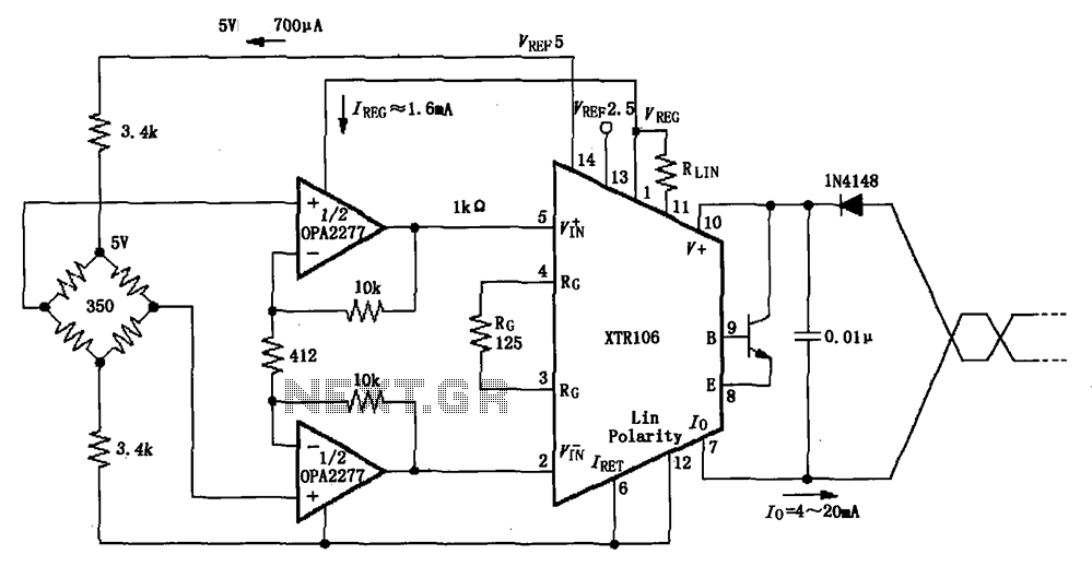
The XTR106, as illustrated in the figure, features two internal source voltages of 2.5V and 5V, enabling it to accommodate a wide range of bridge values without the need for additional circuitry. It can operate with bridge resistances lower...
NOTE: There is no guarantee as to the suitability of said circuits and information for any purpose whatsoever other than as a self-training aid. I.E. If it blows your equipments, trashes your hard disc, wipes your backup, burns your...
S1 and S2 are normally open, push-to-close, momentary switches. The diodes can be either red or green and are used solely for indicating direction. The TIP31 transistors may need to be adjusted based on the motor specifications. It is...