
interfacing large load bank with

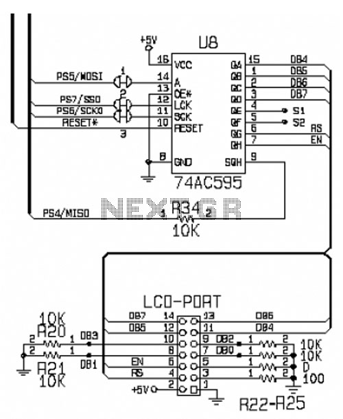
The output port expander circuit for the 8051 microcontroller is designed to manage a large number of solid-state relays, which are essential in applications requiring the control of high power loads. The use of shift registers, specifically the 74LS4094 or the CD4094, allows for the expansion of the output capabilities of the microcontroller, enabling it to control up to 50 relays with minimal complexity in the circuit design.
The circuit operates by utilizing the serial input from the microcontroller, which is then converted into parallel output signals through the shift register. This approach significantly reduces the number of microcontroller pins required for direct relay control, simplifying the overall design. Each relay can be individually controlled by sending specific commands over an RS232 serial connection, allowing for flexible and dynamic control of the load bank.
The load bank itself can be configured to switch high voltages and currents, making it suitable for various industrial applications. The relays function as switches, enabling or disabling power to connected loads based on the commands received from the microcontroller. This setup is particularly beneficial in scenarios where multiple loads need to be controlled simultaneously or in a sequential manner.
In addition to the primary functionality, the project can serve as an educational tool for students and professionals looking to understand the principles of interfacing microcontrollers with external devices. It provides practical experience in working with shift registers, serial communication, and relay control, which are fundamental concepts in the field of electronics and embedded systems.This project is output port expander of microcontroller 8051. In this project we will learn, how to interface a large load bank with microcontroller 8051. In this load bank project, up to 50 solid state relays are interfaced with microcontroller using shift register 74LS4094 TTL IC, student can use CD4094 CMOS IC, any of them will work here fine. The basic purpose of this microcontroller project is to learn the interfacing of shift register for output port expansion. This project is for bank load which could be in the form of a large number of relays to switch ON or OFF the high voltages and high current loads.
The same project can be used for the interfacing of solid state relays. This is improved version of last project ( Control solid state relays up to 50 with microcontroller 8051 ) in which latches were used. The wiring diagram of that project was complicated. Thus by using serial to parallel shift register ICs, the circuit diagram is quit simple now. To turn ON any individual LED for load, command is n01 or N01 from RS232 serial communication from PC, you can use hyper terminal for testing the project or you can write your own code in any PC language.
relay switch atmel microcontroller51, interfacing relays with 8051, PLC output on relay switch, how a relay is behave like a switch, load bank consisting of many relays, bank load of relays and switches, data flow diagram of modem data rate analysis, industrial electronics circuit diagram 🔗 External reference
Related Circuits
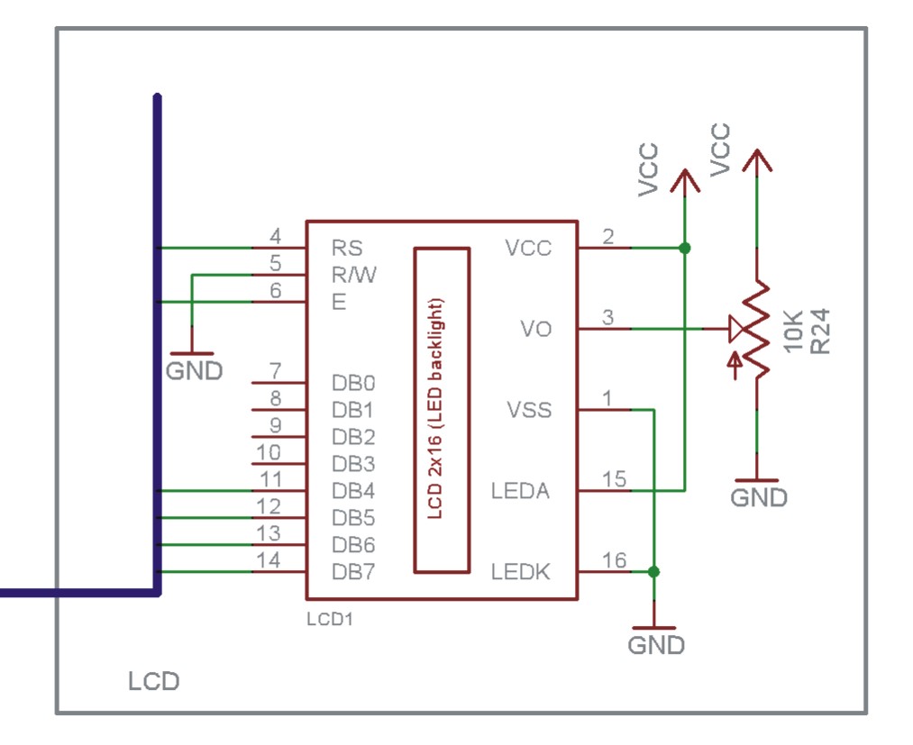
The EN line is referred to as 'Enable'. This control line is utilized to indicate to the LCD that data is being sent. To transmit data to the LCD, the program must ensure that this line is low (0),...
This article provides insights on how to interface infrared (IR) remote controllers with a computer. Possible applications include controlling a computer using a TV remote or managing a VCR through a computer. The circuit discussed was initially shared in...
The load described here is capable of handling up to 10 watts of RF power for a couple of minutes and is designed for the widely used 50 ohms impedance. It consists of ten parallel connected 560 ohms 1...
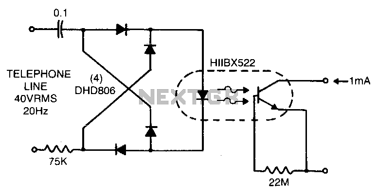
Low line current loading is provided by the H11BX522 photodarlington optocoupler, which delivers a 1 mA output from a 0.5 mA input. The H11BX522 is a photodarlington optocoupler that is designed to provide electrical isolation between its input and output...
This circuit is designed for interfacing an I/O keypad and an LCD, allowing students to gain hands-on experience with basic I/O device interfacing using the HCS12 microcontroller mounted on the CML12S-DP256 development board. The keypad utilized in this circuit...
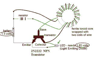
This circuit is known as the Joule Thief. For those unfamiliar with it, an image of the circuit is provided. The Joule Thief is a minimalist circuit designed to extract usable voltage from a low-voltage power source, such as a...