
Electronic Dice circuit
The circuit design employs a microcontroller or a dedicated random number generator IC to produce random values in the specified range. The push button S1 serves as the input mechanism for user interaction, triggering the generation of a random number upon being pressed.
Each of the six LEDs is connected to a digital output pin of the microcontroller, and a current-limiting resistor is used in series with each LED to prevent excessive current flow, ensuring their longevity. The microcontroller is programmed to generate a random integer between 1 and 6 when the button is pressed. The corresponding LED for the generated number is then activated.
The timing for the LED illumination is controlled by a delay function in the microcontroller's firmware, which allows the selected LED to remain lit for a predetermined period of five to ten seconds. After this time elapses, the microcontroller switches off the LED and resets the system, preparing for the next button press.
Power supply considerations are essential; the circuit can be powered by a standard battery or a DC power source, ensuring the voltage levels are suitable for the microcontroller and LED operation. Proper grounding and decoupling capacitors may also be included to enhance circuit stability and performance.
In summary, this random number generator circuit effectively simulates the randomness of dice rolls using a simple user interface and visual feedback through LEDs, making it suitable for various applications, including games and educational tools.The particular circuit is substantially a generator of accidental numbers, from 1 until the 6. The clue him we see in a line from led, that each one corresponds also in a number from the 1-6, if push and leave, the S1 (push button). This movement corresponds in a movement of dice. The led that it turned on will remain turned on for five until ten seconds and afterwards it will black out, waiting for the next movement..
🔗 External reference
Related Circuits

The thyristor control circuit includes a bridge circuit designed to regulate the temperature in the contactor coil KM, along with a secondary winding that functions as a power protection device. It comprises a thermistor (R:., Rt3) and a resistor...
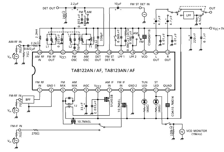
A simple low-power AM/FM radio receiver electronic project can be designed using the TA8122 integrated AM/FM receiver, manufactured by Toshiba Semiconductor. This radio receiver circuit can be utilized for portable radio applications or similar devices. The TA8122 radio receiver...
This page will be updated as material becomes available. This new system will essentially replace the original BCD design, which was created by WB6IGP and N6IZW and was featured in the ARRL UHF/Microwave Project Manual. Their work was later...

877 ~ 924MHz RF2152 power amplifier circuit diagram. The RF2152 is a high-performance power amplifier designed for applications in the 877 to 924 MHz frequency range. This amplifier is typically used in various RF communication systems, including wireless networks and...
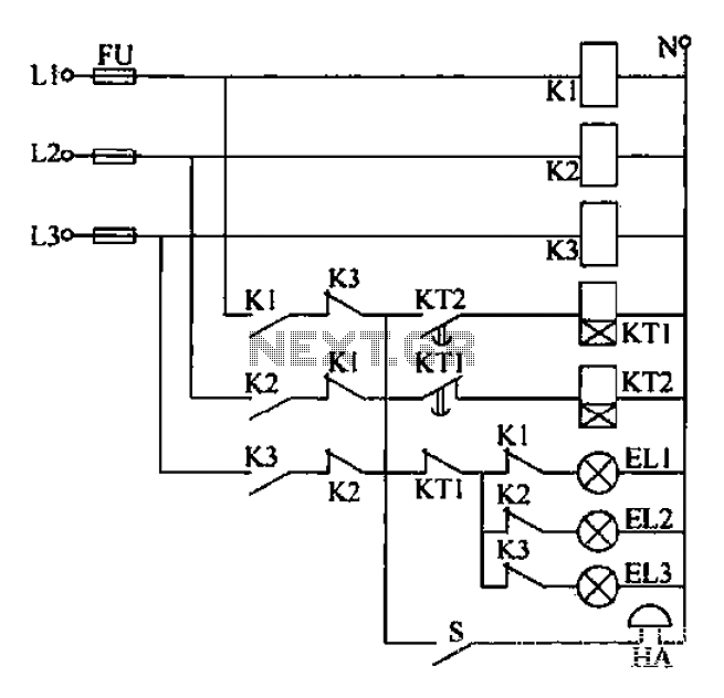
Any power supply and distribution sector should include phase sequence detection to ensure that the power supply phase sequence remains stable and unchanged. Additionally, any irreversible electromechanical product should also incorporate phase sequence detection to verify the phase sequence...
The circuit above is a canonical AC coupled common emitter amplifier, which is typically used as a linear amplifier rather than a switch that activates when the input exceeds a certain level. The AC coupled common emitter amplifier is...