
Power phase sequence display circuit
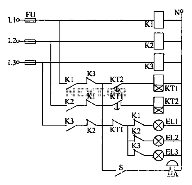
The described circuit for phase sequence detection in a three-phase power supply system is crucial for ensuring operational safety and reliability. The circuit employs a voltage rectifier (UR1) to convert the AC voltage from the power supply into DC voltage. This DC voltage is then used to charge capacitor C2 through resistors R3 and Ri. The neon bulb EL1, which indicates the correct phase sequence, is activated when the voltage across C2 reaches a specific threshold known as the ignition voltage.
The operation is cyclical; once EL1 lights up, it discharges C2, causing the voltage to drop. When the voltage falls below the threshold, EL1 turns off, allowing C2 to recharge again. This cycle continues, creating a visual indication of the correct phase sequence through a steady green light. The frequency of the flashing can be adjusted by changing the values of resistors RL and capacitors C2 and Shu, which affect the time constant of the charging and discharging process.
In contrast, if the phase sequence is reversed, the circuit is designed to activate a different neon bulb, EL2, which emits a red light to indicate an incorrect phase sequence. This dual-indicator system provides a clear visual cue for operators, enhancing safety and preventing potential damage to equipment that could arise from incorrect phase connections. The circuit is essential for any three-phase power supply system, particularly in industrial settings where the integrity of power supply phases is critical for the operation of electromechanical devices.Any power supply and distribution sector should phase sequence detection Huan Jj means to ensure stable power supply phase sequence unchanged. Any irreversible electromechanica l product itself should also have the phase sequence detection means in order to put into operation before the host power supply phase sequence is determined to meet the requirements. Three-phase power supply phase sequence indication circuit as shown when a forward phase sequence, voltage rectified by UR1 on R3, and through Ri charging C2, C2 when the voltage reaches neon EL1 Kai when the ignition voltage, EL1 lit., green.
Cz by EL1 discharge; C2 is lower than the voltage to be a certain value. EL1 off, Cz again charged, while EL1 again lit, C2 refreshing. Again and again, bright green neon EL1 constantly busy, Similarly, when the inverse when the phase sequence, only the red flashing neon EL2. Adjustment RL, C2 and Shu, G time constant, you can adjust the frequency of flashing neon.
Related Circuits
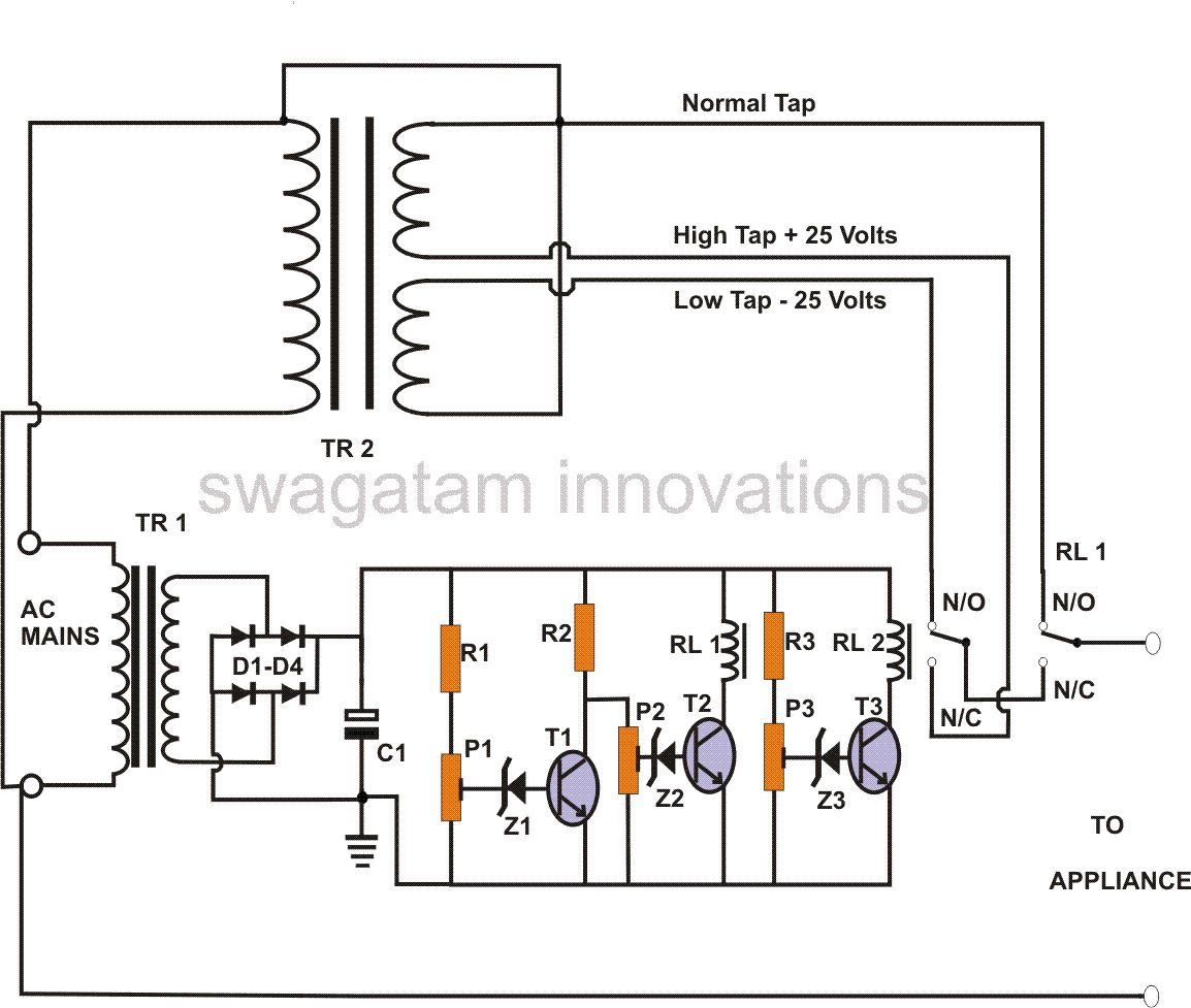
This power stabilizer circuit utilizes one relay to select either the high or low tap from the stabilizer transformer at a specific voltage level. The second relay maintains the normal mains voltage, but when a voltage fluctuation occurs, it...
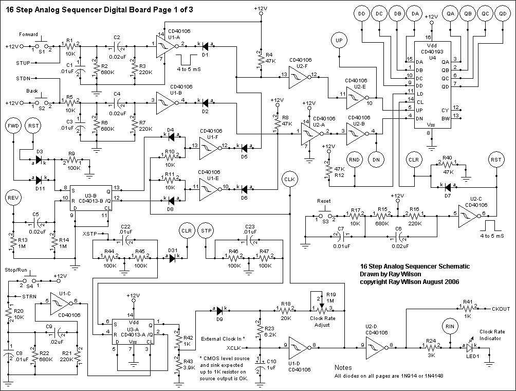
This project is classified as intermediate to advanced, and it is not recommended for beginners in synthesizers or electronics. The circuit and some explanations are provided, assuming prior experience in project building, troubleshooting, and electronics. Ownership of electronic equipment...
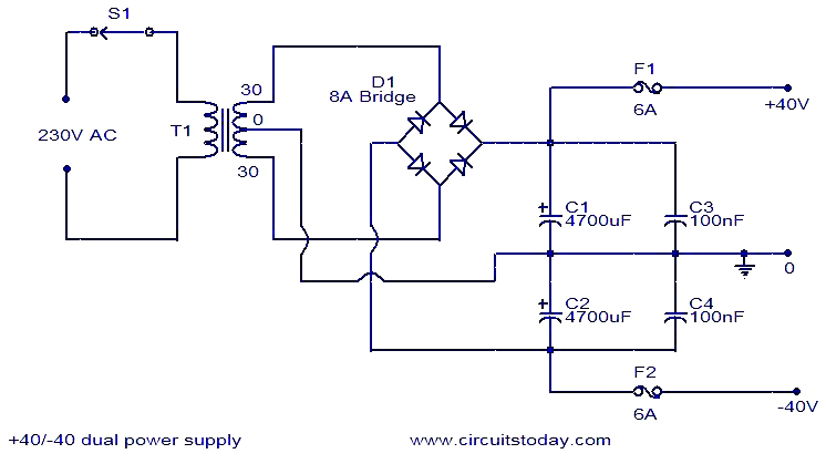
This 40V dual power supply circuit was designed to power a 150 Watt amplifier circuit. The transformer T1 steps down the mains voltage, while bridge D1 performs rectification. Capacitors C1 and C2 act as filters, and C3 and C4...
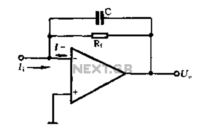
A current-voltage conversion circuit. A current-voltage conversion circuit is designed to transform an input current signal into a corresponding voltage signal. This type of circuit is fundamental in various applications, including sensor interfacing, signal conditioning, and analog-to-digital conversion processes. Typically,...
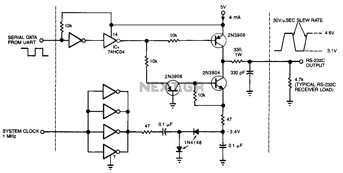
This circuit draws only 4 mA from a 5-V supply while driving a standard RS-232C receiver. The system clock drives a de-de converter that produces -3.4 V. The frequency can range from 0.5 to 8 MHz, but a range...
The ADF4107 Frequency Synthesizer can be used to implement local oscillators in the upconversion and downconversion sections of wireless receivers and transmitters. It consists of a low noise digital phase frequency detector (PFD), a precision charge pump, a programmable...
Warning: include(partials/cookie-banner.php): Failed to open stream: Permission denied in /var/www/html/nextgr/view-circuit.php on line 713
Warning: include(): Failed opening 'partials/cookie-banner.php' for inclusion (include_path='.:/usr/share/php') in /var/www/html/nextgr/view-circuit.php on line 713