
Electronic Die

The electronic die circuit is designed to mimic the behavior of a traditional die while incorporating modern electronic features to enhance functionality and efficiency. The core of the circuit is the free-running oscillator, which generates a stable clock signal that drives the counter and manages the display's illumination. The use of a timer allows the system to enter a low-power standby mode, thereby conserving energy when not in active use. The counter's design, with the ability to switch between counting ranges, adds versatility to the electronic die, accommodating various game requirements. The interaction between the counter and the display decoder is optimized to ensure that the display remains visually appealing and functional, even with the pulsed operation. The choice of components, whether standard or SMD, provides flexibility in design and can cater to different manufacturing preferences. The overall layout and component arrangement are critical for minimizing size while maintaining performance, ensuring that the electronic die remains user-friendly and practical for everyday use.The simplicity of a traditional die makes it exceptionally difficult to create a fully equivalent electronic version, if only because an electronic version requires a power supply and a collection of electronic components that occupy a much larger volume than a normal die. This article describes an electronic die that can be built using normal com ponents or SMDs as desired, and which comes very close to having the same format as a traditional die in the latter case. Despite its simplicity, this electronic die incorporates several interesting features. For instance, the range of spots` can be increased from 1 6 to 0 9 using a jumper, and it has standby function that disables the display approximately 8 seconds after the die has been thrown`, in order to save energy.
The electronic die also uses energy efficiently by driving the display in pulsed mode. As a result of the latter two features, the current consumption of the circuit is approximately 25 mA in use and 12 mA in standby. This means that it can easily be powered by a 9-V battery. The circuit consists of the following parts: a free-running oscillator (IC1a), additional logic for driving the display (IC1c & IC1d), a timer (IC1b), a counter (IC3) and a display decoder (IC2).
The oscillator is very simple. Its frequency, which is determined by R1 and C1, is approximately 225 Hz, with a duty cycle of around 50 60 percent. The signal from the oscillator acts as a clock signal for the counter (via R2) and a blanking signal for the display decoder (via IC1d).
However, the counter will not count as long as the throw` switch (S1) remains closed, since the clock input of IC3 is grounded by S1. The blanking input of the display decoder is driven by a pulse waveform, so the display is in principle illuminated only around 50 percent of the time, but it appears to be constantly illuminated due to the high clock frequency.
The standby mode works as follows. As long as there is a signal on the clock input of the counter (S1 pressed), the output of gate IC1b is low and the display is enabled. If S1 is released, the counter stops and a number will be shown on the display. However, the clock pulses will have charged C2 via D1, and C2 will slowly discharge via R4. After approximately 8 seconds, the output of gate IC1b will go high, causing the display to be blanked.
The design of the counter is relatively simple. It is wired as an up counter by connecting the U/D pin to VCC. The preset inputs (pins 4, 12, 13 and 3) are configured to binary 0001`, and the counter normally has a counting range of 0 9 (pin 9 connected to ground). Diodes D2, D3 and D4, in combination with resistor R5, act as a logic AND gate, so if the value of the counter is greater than 6, the preset value of 1 is latched into the counter and it starts to count again from 1 to 6.
This only happens if jumper J1 is open. If it is closed, the preset pulse on PREN is suppressed and the counter range is 0 9. The A, B, C and D inputs of the decoder IC (IC2) are driven directly by the counter. The series resistors normally used for the individual segments of the display are instead placed in the common-cathode lead (R7 & R8). This has the advantage of allowing the number of resistors to be reduced, although it has the drawback that the brightness of the display depends on the displayed number.
If the segment current is sufficiently large, (light) saturation occurs and this brightness variation is no longer noticeable. The Blank input (BL) controls whether the display is enabled. If you choose to build this circuit using SMD technology, that will not affect the schematic diagram, but it will naturally affect the choice of components.
In this case, SMD components must be used for the resistors and C1, the diodes must be replaced by BAS32 types, and BT versions of ICs IC1 IC3 must be used instead of conventional types. An SMD version of C2 was not used in the prototype, since SMD electrolytic capacitors are expensive, and normally they are only sold in lots of 10, just like other passive components.
It is also recommended to use a socket for the display of the SMD version of the electronic die, to allow the space under the display to also be used and the dimensions of the circuit board to be further reduced. Any desired DC power source providing a voltage of 5 to 15 V can be used as a power supply. Due to the low current consumption of the circuit, a 9-V battery will last quite a long time. 🔗 External reference
Related Circuits
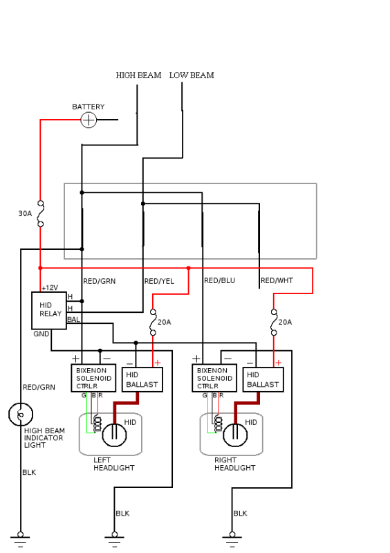
For all those who like to add components to their truck (which is nearly everyone), a thread is being initiated specifically for wiring diagrams. Before posting your diagram... A wiring diagram serves as a visual representation of the electrical connections...
The power supply has been simplified. Power transformers and rectifiers have been omitted, and some components from the MOSFET voltage regulator circuits have been removed, including 1N5242 zener diodes between the source and gate and 10k resistors in series...
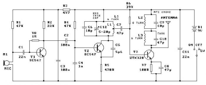
This FM transmitter project is a simple yet effective circuit capable of transmitting signals over a distance of up to 1 kilometer in open air conditions. The circuit employs an RF transistor in the output stage, along with two...
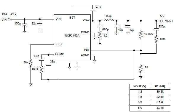
This 5-volt regulated power supply circuit project is designed using the NCP3155 DC-DC switching regulator, which features fully integrated power switches and comprehensive fault protection. The circuit requires only a few external electronic components and delivers a fixed output...
This circuit produces a sound similar to the police siren. It makes use of two 555 timer ICs used as astable multivibrators. The frequency is controlled by the pin 5 of the IC. The first IC (left) is wired...
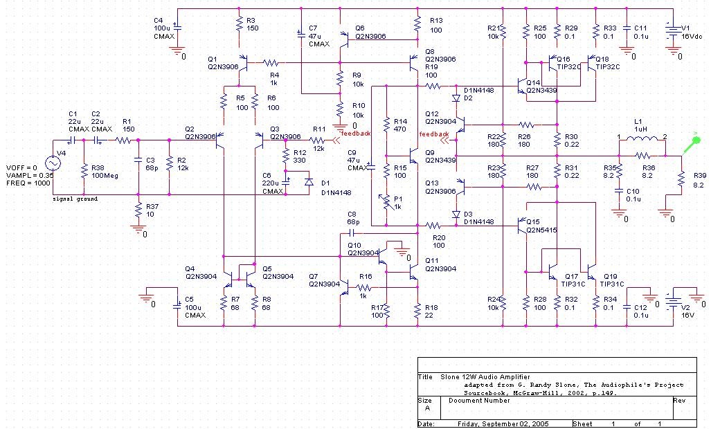
The project involves developing a 12W power amplifier circuit into a fully assembled hard-wired unit. This will require a design cycle and development sequence that includes analysis, simulation, printed circuit board (PCB) layout, board population, hard soldering, and testing....