
Electronics Circuit Application: New Vacuum Tube Amplifier
Here are some minimum ratings: C1G: 100V. C2G: 400V (600V would be better; necessary without the time delay); C3G and C4G: 400V (600V would be better); C3M and C4M: 400V; C5G through C8G: 600V; CBS2, CBS4, CBS6 and CBX1 through CBX3: 100V. The voltage ratings of many of the power supply capacitors are shown on the circuit board wiring diagrams, below.
Some of the feedback connections may be a little hard to trace. ORN goes between the 20 ohm output transformer secondary feedback winding and R3F near TU3. Similarly, VLT goes to R4F near TU4. BLU and BLK on the output transformer secondary speaker winding go to the output tube cathode circuits. BRN and VIO are not used. They are the ultra-linear taps. In the original version of TENA there was a switch to select output tube screen grid connections between BRN and VIO (UL mode) and GRN and YEL (triode mode).
Input stage TU1 is a simple voltage gain stage with local negative feedback, derived from the R1B, R1C voltage divider. It is capacitively coupled to split load phase inverter TU2. The capacitor has an unusually low value- 0. 01 µF- because TU2 has an exceptionally high input impedance- several Megohms. The advantage of capacitive coupling is that it allows the voltage level in TU2 to be set for maximum output and it allows the ac current in TU2 to be precisely equal to, but 180 degrees out of phase with, the current in TU1.
The net ac current drawn by these two tubes from V+420 is therefore zero. This is an effective way of isolating the audio signal from the power supply, which doesn`t need to supply ac current. In conventional designs ac signal often has to flow through electrolytic capacitors, which are grungy leaky devices with memory- harmful to audio quality.
I designed TENA to draw zero net ac current from all power supply outputs (easy to do in a push-pull design), at least up to the power level where one of the output tube pairs starts cutting off. We chose the Plitron toroidal transformer because of its exceptional bandwidth: -3 dB at over 200 kHz, the result of high primary inductance (the good stuff) and low leakage inductance (the bad stuff- kind of like HDL and LDL cholesterol)- much better than can be achieved with a conventional EI transformer.
High bandwidth is important because output transformers have an intrinsic second order rolloff, which can make them unstable in the presence of negative feedback unless careful phase compensation is applied (see Feedback and Fidelity). Phase compensation reduces the bandwidth, which is not a problem with the Plitron toroidal transformers.
But this bandwidth comes at a price- toroidal transformers are much less tolerant of dc-imbalance than EI transformers; they may saturate at dc imbalances as l 🔗 External reference
Related Circuits
In personal electronics and computer audio systems, the SSM2167 is a complete and flexible solution for conditioning microphone inputs. It is also very good for various applications. The SSM2167 is an integrated circuit specifically designed for microphone preamplification and audio...
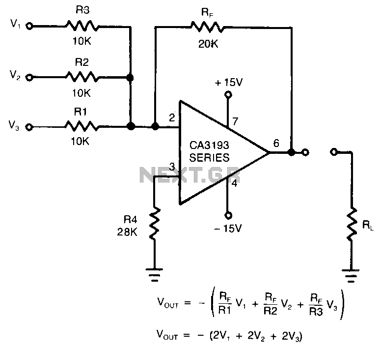
This circuit utilizes a CA3193 BiMOS operational amplifier. The input noise of the amplifier is influenced by the resistor network formed by Rp, Rl, R2, and R3. The gain provided by a single input channel is determined by the...
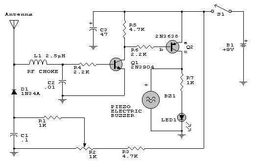
This electronic RF detector project is constructed using common transistors and a few standard electronic components. The RF detector is capable of responding to RF signals below the standard broadcast band and extending to over 500 MHz, providing both...
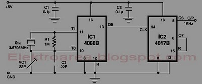
This circuit is designed for accurate time-base generation utilizing the commonly available 3.5795 MHz crystal, which is frequently used in telecommunication equipment. A crystal-based oscillator combined with a divider IC chain or a similar circuit, such as an ASIC,...
To achieve optimal performance as a low noise, high input impedance device, the preamplifier and tone control utilize JFET technology. The circuit is designed to minimize harmonic distortion levels. The use of Junction Field Effect Transistors (JFETs) in the preamplifier...
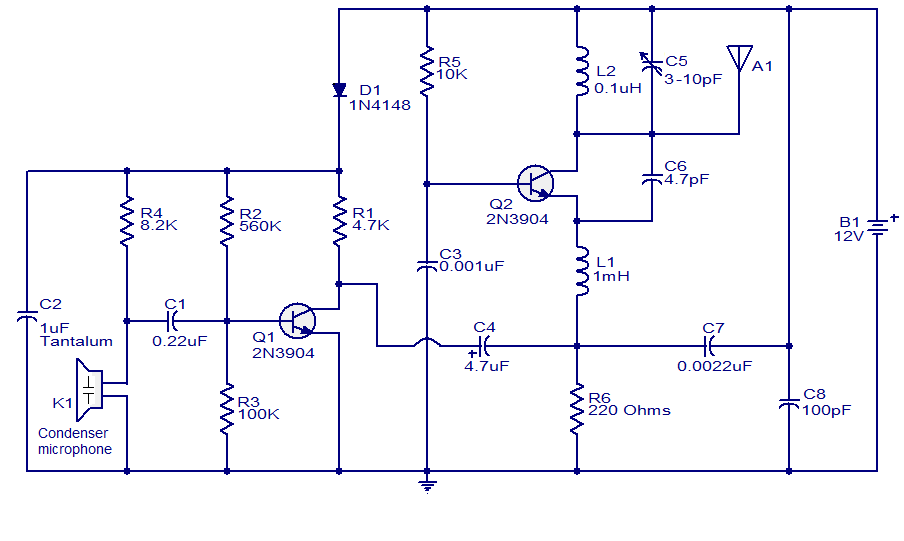
The FM transmitter circuit presented is both stable and simple. With an adaptive antenna, it can achieve a transmission range of approximately 200 meters. This transmitter was developed this year and has yielded positive results. The circuit operates using...