
Electronic Horn
The electronic horn circuit operates by utilizing a combination of transistors and operational amplifiers to generate sound. The LM3900 IC serves as a versatile component, allowing for the creation of various audio signals through its four operational amplifiers. The first op-amp is specifically designed to emulate the sound of a telephone ringing, making it suitable for intercom applications. The frequency modulation of the generated tone is achieved through a wandering voltage generator, which introduces variations in the output tone, providing a more dynamic sound.
In the electronic siren configuration, the circuit mimics the characteristic sound of a police siren by modulating the output frequency. The initial state of the circuit, where the capacitors are discharged, ensures that the transistors remain off until the push button is activated. This design choice allows for a controlled start-up of the sound generation process, preventing unintended activation.
The HT2884 IC enhances the circuit's capabilities by enabling the production of multiple sound effects. The diversity of sounds, ranging from laser guns to bomb detonations, broadens the application spectrum of this circuit, making it suitable for various sound effect requirements.
For the car horn modification, the provided schematic allows for straightforward integration into existing automotive systems. The component values specified ensure that the circuit operates efficiently within the intended voltage range, providing a reliable sound output.
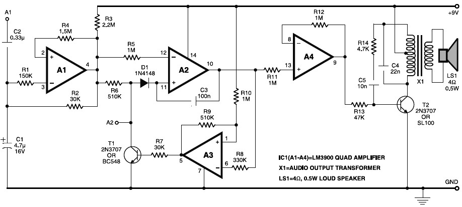
Lastly, the ticking bomb sound generator circuit exemplifies another application of simple electronic components to create sound effects. By adjusting the potentiometer, users can modify the frequency of the ticking sound, adding a layer of customization to the circuit's operation. This approach demonstrates the versatility of basic electronic components in producing a wide range of audio effects for different applications.Electronic horn circuit diagram. When power line is switched on, a general/basic tone is produced by transistor T2 and transformer X1, that is frequency-modulated by the wandering voltage generator, which, in turn, is affected by the low-frequency squarewave generator. This is an easy, low cost and easy built circuit of an electronic horn which is designed close to quadruple op-amp IC LM3900 (IC1). IC LM3900 has four independent operational-amplifiers (A1 through A4) having a large output voltage swing. It is able to operate at up to 32V DC. The 1st op-amp (A1) is designed. This is really a very simple home telephone ring tone generator circuit which is built with applying only several electronic components / parts.
It generates simulated telephone ring tone and requires only DC supply with 4. 5V DC to 12V DC voltage. One may possibly use this circuit in ordinary intercom or phone-type intercom. The sound. This is Electronic Siren circuit diagram. The sound produced imitates the rise and fall of an American police siren. When first switched on the 10u capacitors is discharged and both transistors are off. When the push button switch is pressed to 10u capacitor will charge via the 22k resistor. This voltage is applied to the. All sounds in this circuit are generated by HT2884. There are 8 different sound effect can be produced that are 2 lazer guns, 1 dual tone horn sound, 2 bomb sounds, 2 machine gun sounds and a rifle shot sound. Note: Power is a 3 Volt battery, but the IC will work with any voltage. The following diagram is the schematic diagram fo Car Horn, you may try this circuit for your car modification.
:) Components List: R1 = 68K R2 = 2K2 R3 = 56K R4 = 3K3 R5, R6 = 4K7 R7 = 10K Pot/trimpot C1, C2 = 22nF C3, C5 = 100nF C4 = 1nF C6 = 220 µF/25V IC1, IC2 =. Here the low cost and easy build circuit of ticking bomb sound generator. This circuit generates a sound matching to a loud clicking clock. The frequency of the tick is altered through the 220k potensiometer part. The circuit gets going by charging the 2. 2uF and when 0. 65v is on the base of the NPN transistor, . 🔗 External reference
Related Circuits
The allowable reduction in system performance. For a fire control radar, the acceptable degradation is usually expressed as a reduction in range; for example, the maximum lock-on range might be degraded by 25 percent without loss of essential defense...
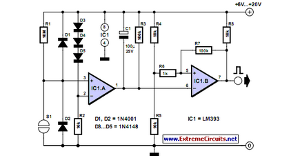
Mechanical contacts have the disadvantage that they wear out. That is why it is practical to use an electronic touch switch in some situations. The electronic touch switch serves as an effective alternative to mechanical contacts, addressing the issue of...
This project takes advantage from -HOLD input, which is connected to push-button P1. As long as the -HOLD input is low, truth table's timeouts have no effect because this input serves to disable any state change provoked by timers....
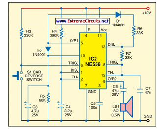
This circuit activates the car horn when the vehicle is in reverse gear. It utilizes a dual timer NE556 to generate the necessary signals. The described circuit employs a dual timer IC, specifically the NE556, which is a versatile component...

The solar orientation circuit employs a comparator with window control to maintain engine idle as long as the two LDRs (light-dependent resistors) are exposed to equal illumination. In this scenario, half the supply voltage is applied to the non-inverting...
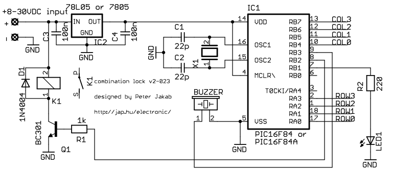
This is my electronic combination lock to use with an outdoor gate. The functionality is implemented in software. It turns on a relay (usually to open a door) for a few seconds if someone enters the valid code. This...