
System for solar orientation using common electronic parts

The solar orientation circuit is designed to optimize the alignment of a solar panel or similar device by utilizing two LDRs, which are sensitive to light intensity. The core component of this circuit is a comparator configured to operate with a window control mechanism. In typical operation, both LDRs are connected to a voltage divider, ensuring that when they receive equal illumination, the voltage at the non-inverting input of the comparator (A1) and the inverting input of the second comparator (A2) remains balanced at half the supply voltage.
When the sun moves, the intensity of light on the LDRs changes. This variation in light causes a difference in the resistance of each LDR, which in turn alters the voltage levels at the inputs of the comparators. If one LDR receives more light than the other, the voltage at the non-inverting input of A1 will exceed the threshold set by the inverting input of A2, resulting in a change in the output state of the comparator.
The output of the comparator can be used to control a motor or actuator that adjusts the position of the solar panel. If the output indicates that LDR R1 is receiving more light, the system will trigger the motor to rotate counterclockwise to realign the panel towards the sun. Conversely, if LDR R2 receives more illumination, the system will adjust the motor in the opposite direction. This feedback mechanism allows for continuous adjustment, ensuring that the solar panel remains optimally oriented to capture the maximum amount of sunlight throughout the day.
In summary, the solar orientation circuit effectively utilizes a comparator and LDRs to maintain optimal alignment with the sun, enhancing the efficiency of solar energy collection through automatic adjustments based on light intensity variations.The solar orientation circuit uses a comparator with window control that maintains engine idle as long as the two LDR`s (photoresist) are subjected to the same illumination. In this case, half the voltage is applied to the noninverting input of A1 and A2`s inverting input. When the sun`s position changes, lighting affecting LDR R1 and R2 sites is different, the comparator input voltage window is not half the supply voltage, the comparator output so that the engine generates information for the purposes of direct or rotate counterclockwise counterclockwise. 🔗 External reference
Related Circuits
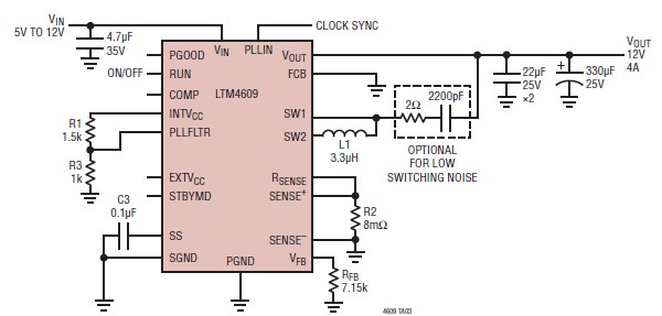
A very simple, high-efficiency switching mode buck-boost power supply circuit can be designed using the LTM4609 switching regulator IC. This circuit will provide a fixed output voltage of 12 volts. As illustrated in the schematic, the switching power supply...

A solar-powered watering system has been proposed to irrigate plants daily using water collected in butts located by the greenhouse. This project has been under development for a considerable time and is now being revisited with the aim of...
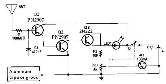
This ion detector circuit is designed to sense static charges and free ions present in the air. It is capable of detecting the presence of free ions, static electricity, or high voltage leakage. The project utilizes a short whip...
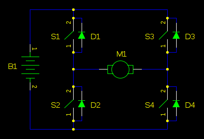
In motor control circuits, precautions must be taken to prevent the motor from feeding back into the power supply, which can cause the supply voltage to rise and potentially damage components. However, unless an external force is accelerating the...
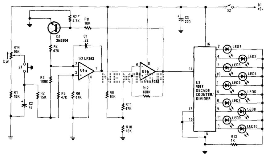
R14 is configured to establish an initial "starting" speed for the oscillators U1A and U1B. As capacitor C2 charges, the oscillation gradually slows down during the discharging phase of C2, creating a roulette-wheel effect on LED S1 through resistor...
This is a simplified schematic for the Solar Lifeforce. The design eliminates the expression/CV output features and the toggle for the buffer, making it a straightforward circuit. It may benefit from adding small capacitors between R5 and ground, as...