
Electronic lark sounds circuit
The described electronic circuit utilizes a sound synthesis approach to emulate the vocalizations of birds, responding dynamically to ambient lighting changes. The core component of this circuit is a microcontroller or sound generator IC, which is programmed to produce different sound patterns resembling various bird calls. The microcontroller receives input from a light sensor, such as a phototransistor or a light-dependent resistor (LDR), that detects the intensity and type of ambient light, particularly neon lighting.
As the light intensity varies, the microcontroller processes this information and adjusts the output sound frequency and modulation accordingly. This results in a range of tones that mimic the natural variability of bird sounds, creating an engaging auditory experience. The circuit may include additional components such as capacitors for filtering, resistors for biasing, and possibly a digital-to-analog converter (DAC) if high-fidelity sound reproduction is required.
Power supply considerations are also essential, as the circuit must operate efficiently under varying conditions. A regulated power supply, possibly utilizing a battery or an AC adapter, ensures stable operation of the microcontroller and sound output components.
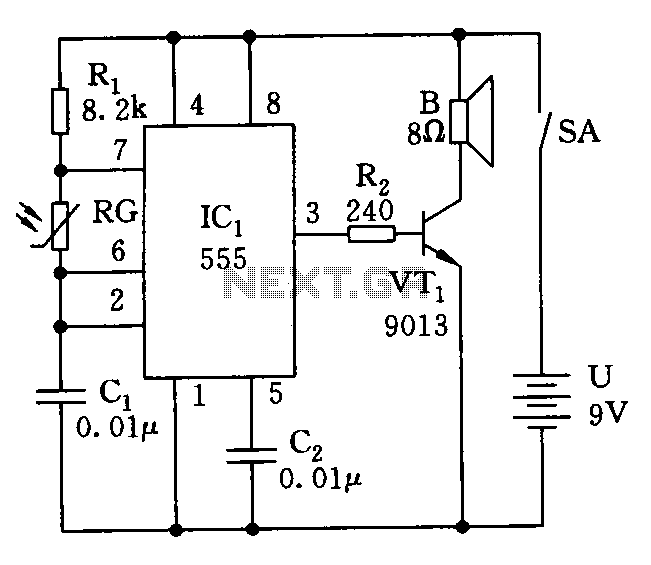
The schematic diagram of this circuit should clearly illustrate the connections between the light sensor, microcontroller, sound output module (such as a speaker or piezo buzzer), and the power supply. Proper grounding and decoupling capacitors should be included to minimize noise and ensure reliable operation.The electronic circuit birds under different lighting, especially in the vagaries of the neon light irradiation, can be issued fluctuated, changing tone sound of birds, the sound is constantly changing. Its circuit is shown.
Related Circuits
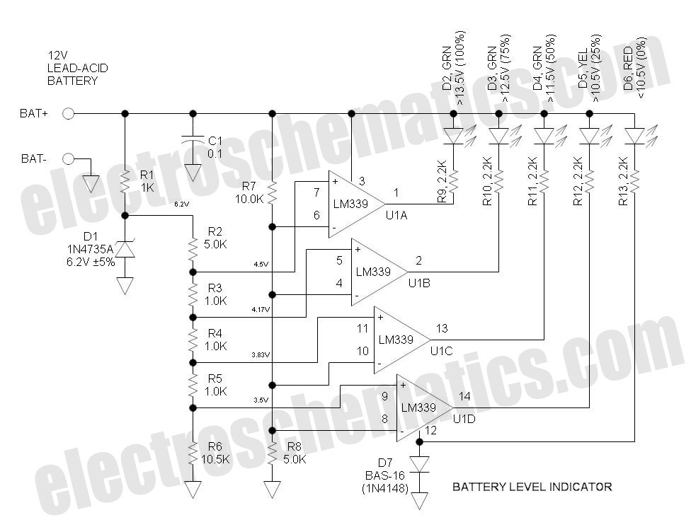
This battery level indicator features five LEDs that illuminate progressively as the voltage increases: Red indicates power connection (0%), Yellow signifies voltage greater than 10.5V (25%). The battery level indicator circuit utilizes a series of five light-emitting diodes (LEDs) to...
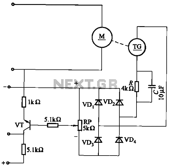
The capacitor C is part of the speed differential negative feedback system. The adjustment potentiometer RP allows for changing the amount of negative feedback. Both components can be utilized simultaneously within the circuit. The voltage (or speed) will only...
The circuit of automatic emergency light presented here has the following features: 1. When the mains supply (230V AC) is available, it charges a 12V battery up to 13.5V and then the battery is disconnected from the charging section....
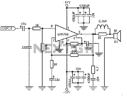
The NS LM4766, launched by a US company, is a two-channel power amplifier integrated circuit. Each channel can output an average power of 40W at an 8-ohm load, with distortion levels lower than 0.1%. It is part of National...
The LM1875 is a monolithic audio amplifier that provides very low distortion and high-quality performance for audio amplifier projects. The LM1875 delivers 20 watts into loads of 4 Ohms or 8 Ohms. The LM1875 audio amplifier is designed for applications...
This remote transmits a tone using an infrared LED. This tone is decoded by the receiver. Since the receiver only switches when it "hears" the tone, there are no accidental activations. The described circuit consists of a remote control unit...