
Infa-Red Remote Control circuit
The described circuit consists of a remote control unit and a corresponding receiver unit. The remote control utilizes an infrared (IR) LED to emit a modulated signal, which encodes a specific tone. This modulation allows the receiver to distinguish the intended signal from background noise or interference, ensuring accurate communication between the two devices.
The infrared LED in the remote is driven by a microcontroller or a dedicated tone generator circuit. The modulation frequency can be selected based on the application requirements, typically falling within the range of 30 kHz to 40 kHz. The choice of frequency is crucial as it must be compatible with the receiver's detection capabilities.
On the receiving end, an infrared photodiode or phototransistor is employed to detect the incoming IR signal. This component is connected to a signal processing circuit that includes a band-pass filter, which helps to isolate the desired modulation frequency from any ambient light or other noise sources. When the receiver detects the specific tone, it activates a switching mechanism, such as a relay or a transistor, to perform the intended action, such as turning on a device or triggering an event.
The design ensures that the receiver only activates upon receiving the correct tone, thereby preventing accidental activations caused by false signals. This feature enhances the reliability and efficiency of the remote control system, making it suitable for various applications, including home automation, security systems, and remote operation of electronic devices.his remote transmits a tone using an infa-red LED. This tone is decoded by the receiver. Since the receiver only switches when it "hears" the tone, there are no accidental activations.. 🔗 External reference
Related Circuits
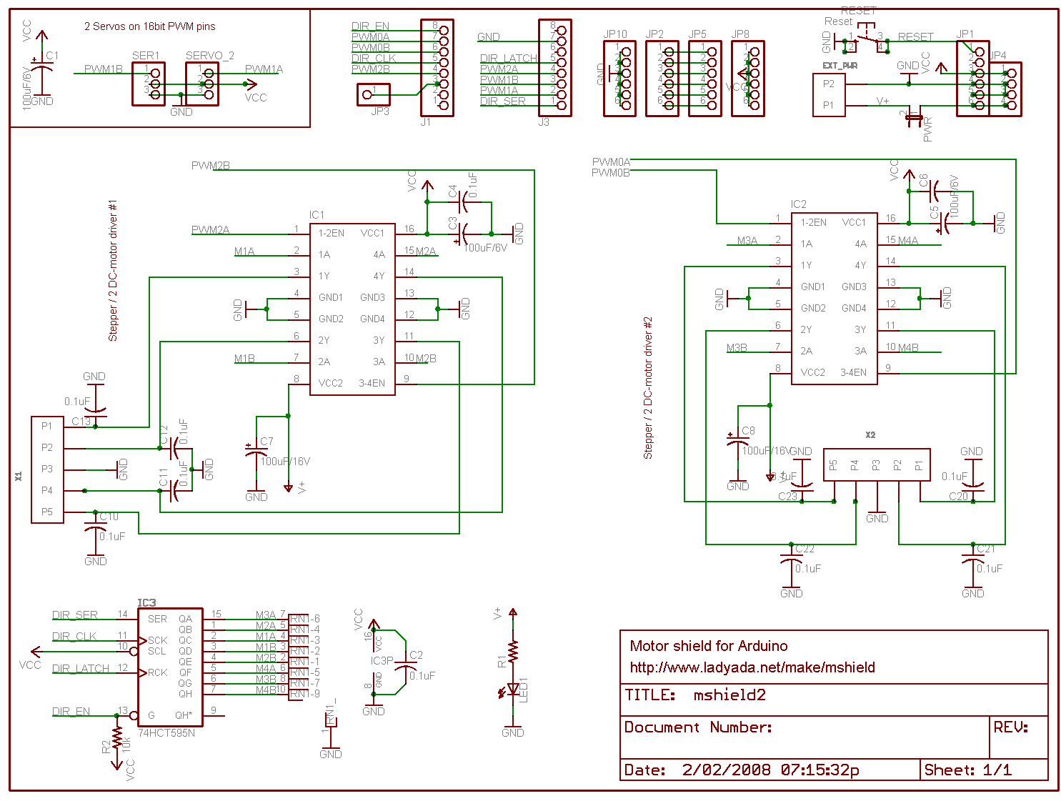
Arduino is an open-source electronics prototyping platform that features flexible and user-friendly hardware and software. It is designed for artists, designers, hobbyists, and anyone interested in creating interactive objects or environments. Arduino can sense the environment by receiving input...

This is a circuit for controlling the speed of small DC motors; it works nicely as a speed controller for an HO or N gauge model railroad. More: The left half of the 556 dual timer IC is used...

This circuit is designed to activate a camera shutter. Grounding pin 2 of U1 causes pin 4 of U1 to go high, which triggers both timers of the dual timer U1. One output maintains the reset (pin 4) of...
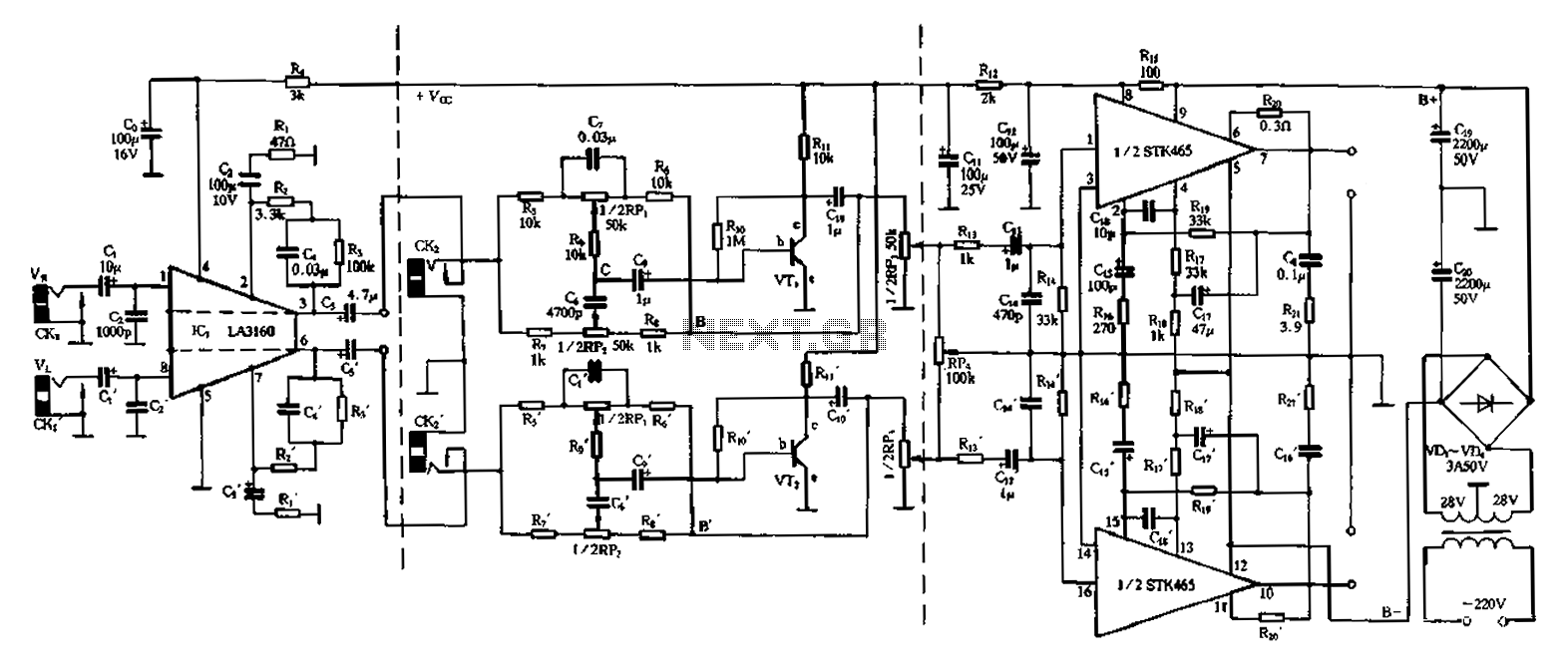
The 50W is a two-channel amplifier featuring a preamplifier and tone control based on the LA3160 integrated circuit. Its external components include the input preamplifier, with C1 serving as the input coupling capacitor. The circuit incorporates a high-frequency bypass...
This magic lamp appears to be an ordinary frosted light bulb with a rather unusual characteristic. Whenever a finger touches the base threads and center contact, the lamp magically lights up without wires. It creates a compelling illusion if...
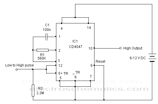
The CD 4047 is a low-power monostable and astable multivibrator that requires only an external capacitor and a resistor to produce output pulses. The CD 4047 integrated circuit (IC) is designed for generating precise timing pulses and can operate...