
electronic liquid detector circuit

The ULN2429A integrated circuit is a versatile component well-suited for liquid detection applications. The circuit operates by utilizing a probe that is placed in the liquid. When the probe is immersed, the resistance changes, allowing the circuit to determine the liquid's presence or absence. This is achieved through the comparison of the probe's resistance with a predetermined reference resistance. The output stage of the circuit can drive various loads, making it adaptable for different applications.
For visual indication, an LED can be connected to the output, which illuminates when liquid is detected. Alternatively, a loudspeaker may be employed for audible alerts, or relays and solenoids can be activated to control larger devices. The inclusion of a capacitor at pin 12 is crucial for smoothing the output signal; without it, the output would be a square wave, which may not be suitable for all applications.
When higher voltage operation is required, the ULN2429A-1 variant can be utilized. This version maintains the same functionality as the ULN2429A but is rated for voltages up to 50 volts, expanding its applicability in more demanding environments. The design of the circuit emphasizes efficiency and reliability, with features such as high output current capacity, which ensures that it can drive loads effectively without overheating.
Additionally, the single-wire probe design simplifies installation and reduces the need for extensive wiring. The circuit's low requirement for external components makes it cost-effective and easy to implement in various projects. Reverse voltage protection is incorporated to safeguard the circuit from potential damage due to incorrect power supply connections, while internal voltage regulation ensures stable operation across different supply voltages.
Overall, the ULN2429A liquid detector circuit is a robust solution for applications requiring liquid level detection, offering flexibility, reliability, and ease of use.This electronic liquid detector circuit diagram is based on the ULN2429A monolithic bipolar integrated circuit designed for detecting the absence or presence of many different types of liquids. The absence or presence of the liquid is determined by comparing the loaded probe resistance (probe immersed in the fluid ) with an internal or external r
esistance. At the output you can connect a LED, incandescence lamp, loud speaker or even such relays or solenoids, but just I you connect at pin 12 a capacitor, to provide a dc output ( typically the output signal is a square wave ). If you need to connect at the output a device that need more than 30 volts you can use the ULN2429A-1 which is identical, but support devices with operation up to 50 volts.
Main features of the ULN2429A are : high output current, AC or DC output, single wire probe, low external parts require, reverse voltage protection, internal voltage regulation. 🔗 External reference
Related Circuits
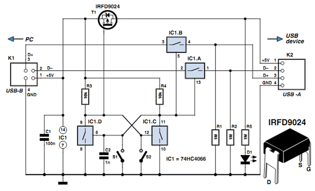
Individuals engaged in the experimentation or development of USB-connected peripheral hardware often find it frustrating to repeatedly disconnect and reconnect the plug to reestablish communication with the PC. This procedure is necessary, for instance, every time the peripheral device...
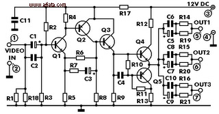
This electronic circuit is a video signal amplifier that provides a broad bandwidth amplifier with a capacity of 5 MHz. It is designed to take video signals from a VCR and amplify them adequately to drive up to three...
The output current of the control circuit must be amplified when the gate current needed to trigger the device exceeds the output current of the control circuit. To achieve the amplification of the control circuit output current, a suitable transistor...
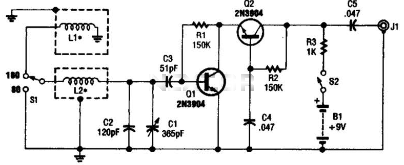
This antenna may assist in minimizing power-line noise. It consists of a plastic hula hoop or conduit with a diameter of 3 feet, which is covered with aluminum foil to serve as a shield for LI and L2. LI...
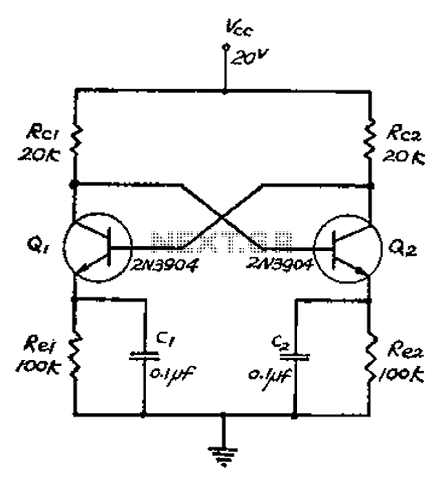
The collector and base-emitter bias of the transistor are directly coupled to each other. Each transmitter circuit controls the capacity conversion function. The emitter generates a triangular wave. The two transistors are not continuously in an active state. Instead,...
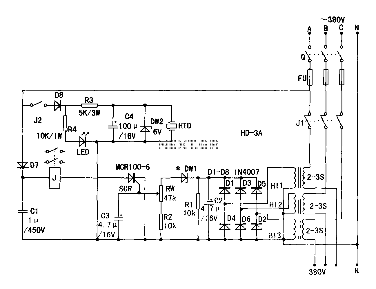
A current transformer H11-3 needs to be constructed. Select a transformer core with a minimum power rating of 2W for the first secondary winding. Use enameled wire with a diameter of 0.12 mm and wind approximately 1000 turns. The...