
usb switch schematic circuit
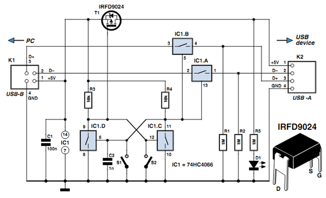
The electronic isolator circuit leverages the 74HC4066 quad analog switch to create a reliable solution for managing USB device connections. The circuit design includes two analog switches dedicated to isolating the data lines, which prevents any unintended communication during power cycling or reset operations. The bistable flip-flop configuration, achieved using the remaining two switches, provides a stable on/off state for the USB connection, preventing accidental disconnections.
The power MOSFET is a critical component in this design, as it controls the power supplied to the USB device. This ensures that the device is powered only when the user intends to connect it to the PC, thereby prolonging the lifespan of both the USB connector and the peripheral hardware. The inclusion of capacitor C2 is essential for initializing the flip-flop state, ensuring that the device remains in a safe "not connected" state upon power-up.
The circuit's design prioritizes user convenience and hardware longevity. By implementing a simple pushbutton mechanism, users can easily manage the connection status of their USB devices, eliminating the need for physical disconnections. The layout can be compactly arranged on a perf-board, making it accessible for hobbyists and engineers alike. Overall, this electronic isolator circuit represents an effective solution for anyone working with USB peripherals, enhancing both usability and durability.Anyone experimenting or developing USB ported peripheral hardware soon be comes irritated by the need to disconnect and connect the plug in order to reestablish communication with the PC. This process is necessary for example each time the peripheral equipment is reset or a new version of the firmware is installed.
As well as tiresome it eventuall y leads to excessive contact wear in the USB connector. The answer is to build this electronic isolator which disconnects the peripheral device at the touch of a button. This is guaranteed to reduce any physical wear and tear and restore calm once again to the workplace.
The circuit uses a quad analogue switch type 74HC4066. Two of the switches in the package are used to isolate the data path. The remaining two are used in a classic bistable flip-flop configuration which is normally built using transistors. A power MOSFET switches the power supply current to the USB device. Capacitor C2 ensures that the flip flop always powers-up in a defined state when plugged into the USB socket (B` in the diagram).
The peripheral device connected to USB socket A` will therefore always be not connected` until pushbutton S2 is pressed. This flips the bistable, turning on both analogue gates in the data lines and switching the MOSFET on.
The PC now recognises the USB device. Pressing S1 disconnects the device. The circuit does not sequence the connections as a physical USB connector does; the power supply connection strips are slightly longer than the two inner data carrying strips to ensure the peripheral receives power before the data signals are connected. The electronic switch does not suffer from the same contact problems as the physical connector so these measures are not required in the circuit.
The simple circuit can quite easily be constructed on a small square of perforated strip-board. The design uses the 74HC(T)4066 type analogue switch, these have better characteristics compared to the standard 4066 device. The USB switch is suitable for both low-speed (1. 5 MBit/ s) and full-speed (12 MBit/s) USB ports applications but the proper ties of the analogue switches and perf-board construction will not support hi-speed (480 MBit/s) USB operation.
🔗 External reference
Related Circuits
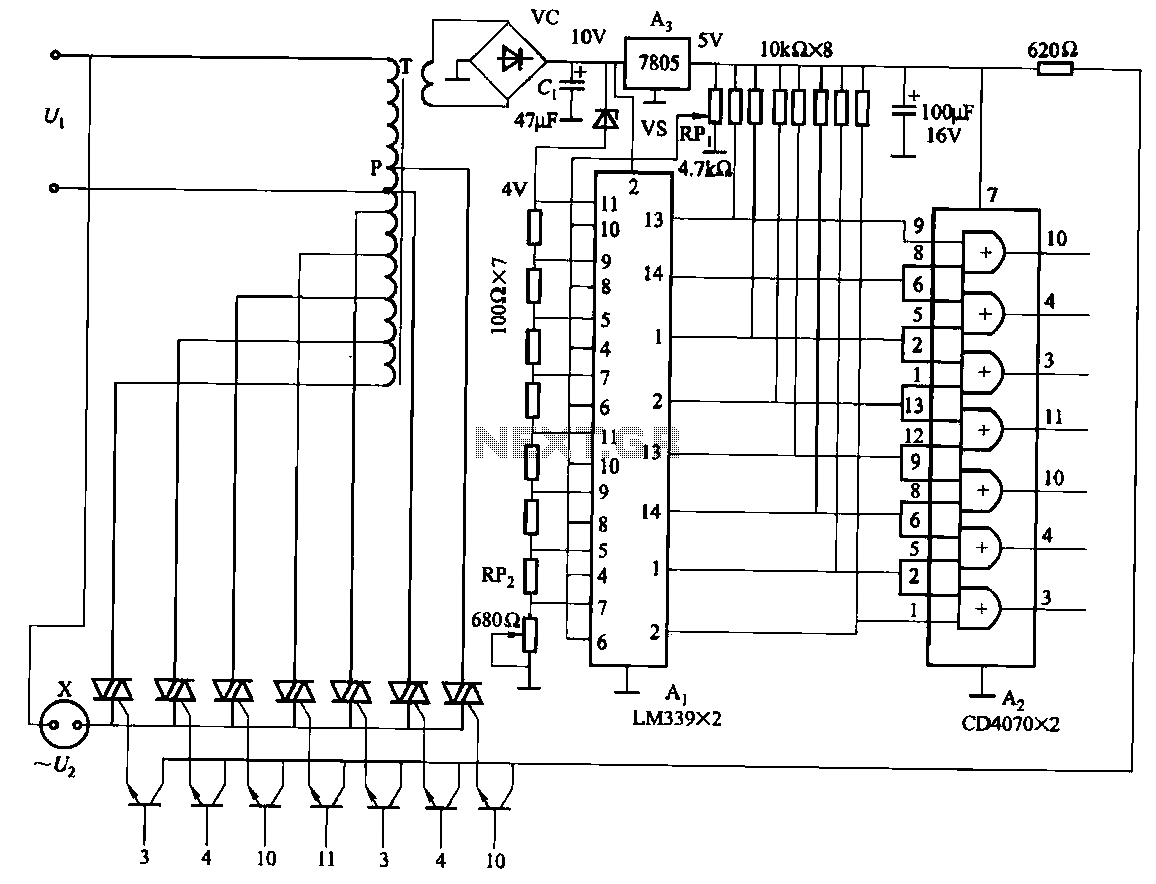
The circuit consists of two LM339 comparators and two CD4070 XOR gate thyristors, along with additional components such as an autotransformer exchange regulator. It also features overvoltage and undervoltage protection. The control range can be adjusted by modifying the...
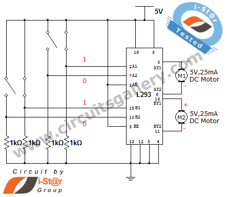
How can a DC motor be rotated in clockwise and counterclockwise directions? This is a common question posed by many robotics beginners. DC motor driver circuits are essential components in robotics workshops. The L293D IC is frequently utilized for...

The circuit depicted involves transistors VT1, VT2, and resistor R1, which form a constant current source for charging capacitor C2 in a linear manner. Transistors VT3, VT4, and resistor R2 create a constant current source for discharging capacitor C2,...

The outputs from the comparators will transition, in sequence, from high to low as the input voltage exceeds the reference voltage applied to each comparator. The output LEDs will activate sequentially as the voltage increases. The inverting inputs of...

The circuit diagram of a lantern dimmer/flasher designed by Tony Van Roon includes the following electronic parts: R1 = 100K, R2 = 100K, R3 = 100K, R4 = 100K, R5 = 3.9K, R6 = 3.9K, R7 = 470, R8...

A preamplifier for magnetic pickups of record players is presented. The uA 741 is utilized as an AC-coupled non-inverting amplifier operating on a single supply. The amplifier gain is determined by the feedback components, where C2 manages the low-frequency...
Warning: include(partials/cookie-banner.php): Failed to open stream: Permission denied in /var/www/html/nextgr/view-circuit.php on line 713
Warning: include(): Failed opening 'partials/cookie-banner.php' for inclusion (include_path='.:/usr/share/php') in /var/www/html/nextgr/view-circuit.php on line 713