
Electronic Lock with 4013
The described circuit operates as a sequential lock system utilizing momentary push-button switches. The primary function is to unlock a mechanism connected to the K1 load, which could represent an electronic lock or relay. The operation relies on pressing the switches in a predetermined order: S1, S2, S3, and S4.
In terms of design, the circuit typically consists of four momentary switches, each connected to a microcontroller or a logic circuit capable of recognizing the sequence of inputs. The microcontroller is programmed to monitor the state of each switch. When a switch is pressed, the microcontroller checks if it is the expected switch in the sequence. If the correct switch is pressed, the microcontroller proceeds to the next expected switch in the sequence.
If an incorrect switch is pressed at any point, the microcontroller triggers a reset condition, which may involve turning off the K1 load and restarting the sequence. This ensures that only the correct sequence will successfully activate the lock mechanism.
To enhance flexibility, the circuit can be designed to accept any combination of four switches, allowing customization based on user preference. The wiring of the switches can be configured in parallel or series, depending on the desired behavior of the circuit.
Additional components may include resistors for pull-down or pull-up configurations to ensure stable switch readings, as well as diodes to prevent back EMF if inductive loads are used. The output to the K1 load can be managed through a transistor or relay, providing a safe interface between the low voltage control circuit and the higher voltage lock mechanism.
In summary, this basic sequential lock circuit offers a simple yet effective method for controlling access based on a specific sequence of user inputs, ensuring security and flexibility in operation.This circuit is very basic to build. To open a the lock which is connected to the K1 Load you must press each momentary switch in the correct sequence. The sequence used in this circuit is S1,S2,S3,S4. If any of the other switches are pressed the circuit will reset and you will need to start over. Depending on how you wire the switches, you can use any 4 switch combination. 🔗 External reference
Related Circuits
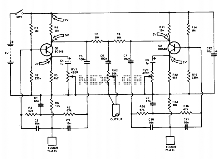
This circuit consists of twin-T sine-wave oscillators. Each oscillator has a filter in the feedback loop. If the loop gain is greater than unity, the circuit will oscillate. Gain is adjusted to be just less than unity. Touching the...
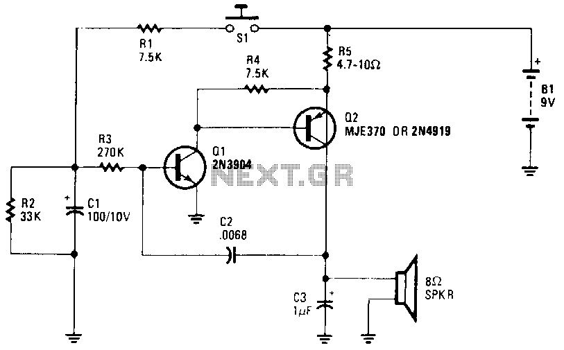
The wailing sound of a siren is generated by a voltage-controlled oscillator (VCO) comprised of transistors Q1 and Q2. Capacitor C2 provides the necessary feedback for the oscillator operation. The oscillator frequency is adjusted by the voltage applied to...
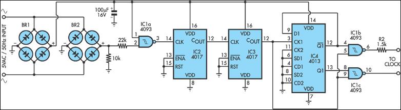
Quartz clocks have dominated timekeeping for the past 20 years but have a cumulative error that can become significant over time. While crystal frequency adjustments can correct some errors, regular resetting is often necessary. In contrast, mains-powered synchronous clocks...
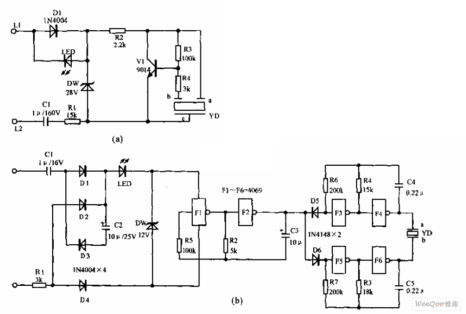
The telephone electronic ringer circuit is illustrated in the provided figure. It features an NPN transistor (either 9014 or 3DG12) as the primary component. The sound device, referred to as YD, functions as both a feedback device and is...
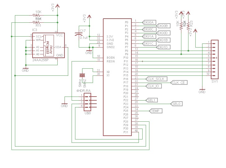
After constructing numerous Nixie Tube Clocks based on online designs, a personal design was developed. This clock utilizes IN-12 Nixie Tubes and an 8-core Propeller Microcontroller. Although the Propeller may be more powerful than necessary for this task, it...

The term VCXO refers to a Voltage Controlled Crystal Oscillator. The frequency of this oscillator can be fine-tuned by varying the control voltage. VCXO clock generators are utilized in a range of applications, including digital telecommunications. VCXO circuits are essential...