
building synchronous clock
The proposed circuit effectively transforms a standard quartz clock into a synchronous clock that relies on the mains frequency, thereby improving accuracy over time. The use of a low-voltage AC plug pack as the power source ensures safety and compatibility with household electrical systems. The integration of bridge rectifiers allows the conversion of AC to DC for powering the circuit while simultaneously generating the necessary timing pulses for clock operation.
The 4093 NAND Schmitt trigger serves a crucial role in shaping the 100Hz signal into a square wave, which is essential for precise timing applications. The cascaded 4017 decade counters further divide the frequency down to a 1Hz signal, suitable for driving the clock mechanism. The 4013 D-type flip-flop is utilized to create timed outputs that can be manipulated to produce the required short pulses for the clock movement, ensuring that the clock's second hand moves accurately without being overloaded.
The addition of limiting resistor R1 is critical to prevent excessive current from damaging the clock movement. Careful selection of this resistor should be based on empirical testing to ensure optimal performance. This design not only enhances the reliability of the clock but also provides an interesting project for electronics enthusiasts looking to repurpose quartz clock movements into more accurate timekeeping devices.The quartz clocks which have dominated time-keeping for the past 20 years or so have one problem: their errors, although slight, are cumulative. After running for several months the errors can be significant. Sometimes you can correct these if you can slightly tweak the crystal frequency but otherwise you are forced to reset the clock at regular i
ntervals. By contrast, mains-powered synchronous clocks are kept accurate by the 50Hz mains distribution system and they are very reliable, except of course, when a blackout occurs. This circuit converts a quartz clock to synchronous mains operation, so that you can have at least one clock in your home which shows the time.
First, you need to obtain a quartz clock movement and disassemble it down to the PC board. For instructions on how to do this, see the article on a "Fast Clock For Railway Modellers" in the December 1996 issue of SILICON CHIP. Then isolate the two wires to the clock coil and solder two light duty insulated hookup wires to them (eg, two strands of rainbow cable).
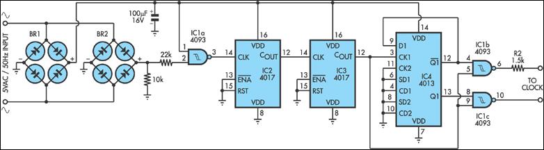
Drill a small hole in the clock case and pass the wires through them. Then reassemble the clock case. To test the movement, touch the wires to the terminals of an AA cell, then reverse the wires and touch the cell terminals again. The clock second hand should advance on each connection. The circuit is driven by a low voltage AC plug pack. Its AC output is fed to two bridge rectifiers: BR1 provides the DC supply while BR2 provides positive-going pulses at 100Hz to IC1a, a 4093 NAND Schmitt trigger.
IC1a squares up the 100Hz pulses and feeds them to the clock input of the cascaded 4017 decade counters. The output at pin 12 of IC3 is 1Hz. This is fed to IC4, a 4013 D-type flipflop, which is connected so that its two outputs at pins 12 & 13 each go positive for one second at a time.
As these pulses are too long to drive the clock movement directly, the outputs are each fed to 4093 NAND gates IC1b & IC1c where they are gated with the pin 3 signal to IC4. This results in short pulses from pins 3 & 10 of IC1 which drives the clock via limiting resistor R1.
The value of R1 should be selected on test, allowing just enough current to reliably drive the clock movement. 🔗 External reference
Related Circuits
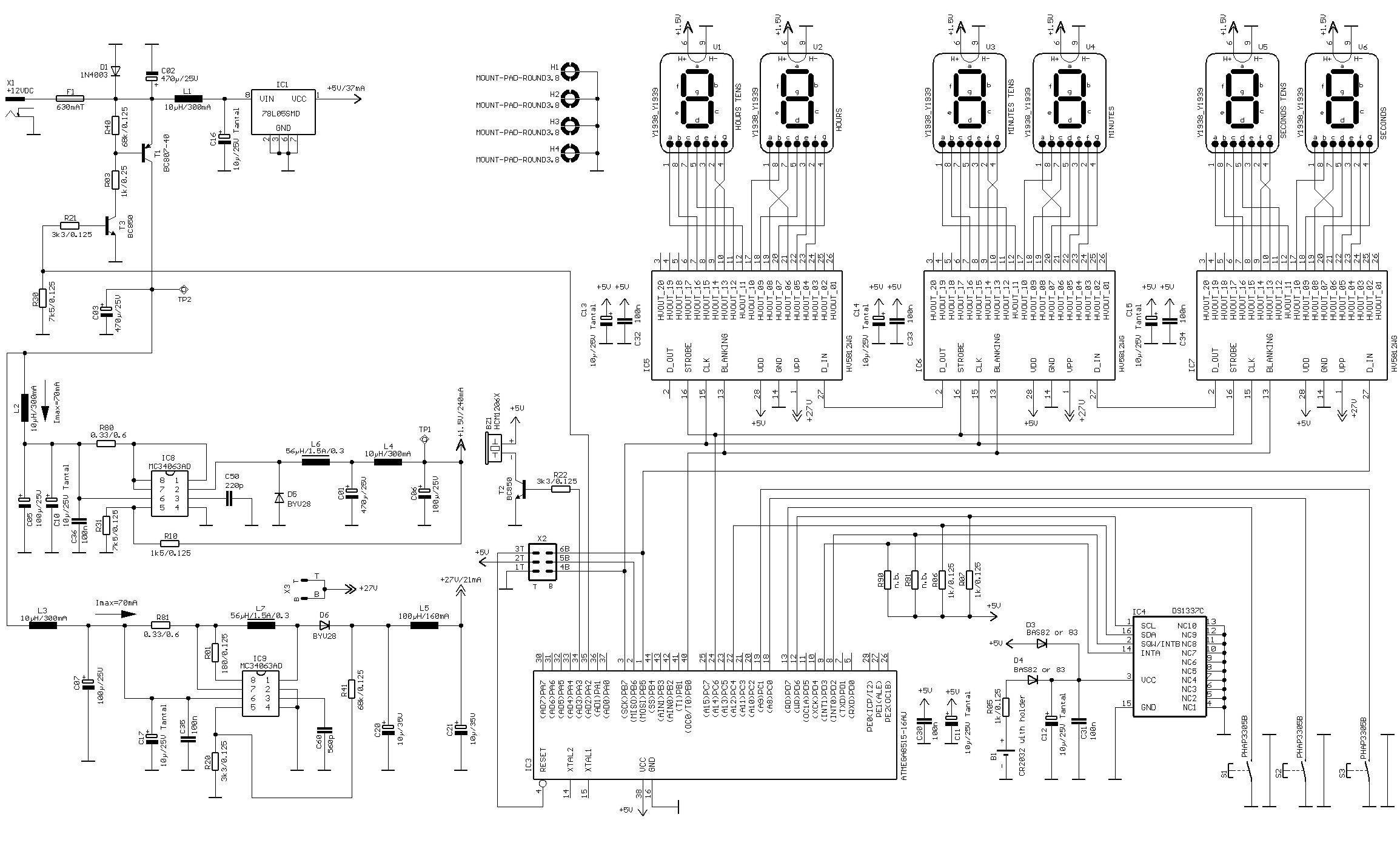
A vacuum fluorescent display (VFD) tube is a type of tube that consists of a hot cathode (filaments) and anodes (phosphor) within a high vacuum environment enclosed in a glass envelope. This clock utilizes tube types 8843 or 8894,...
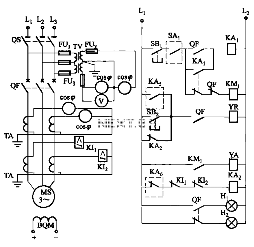
The circuit depicted in Figure 3-186 includes an isolation switch, QF vacuum circuit breakers, YR line for the circuit breaker coil, and YA for the circuit breaker closing coil. Additionally, there is a dashed box representing the excitation device...
This project involves using an EasyDriver stepper motor driver and a 1.8-degree per rotation stepper motor to achieve a motor speed of one revolution per minute. The EasyDriver simplifies the operation, requiring a DC voltage of 7-30V connected to...

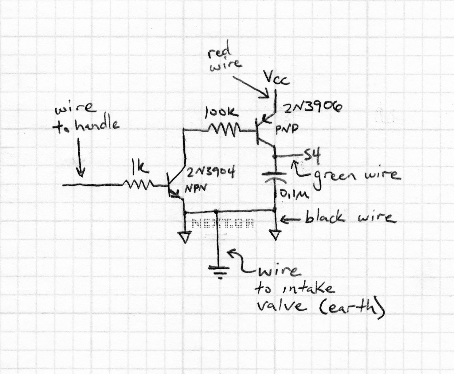
The clock described here is a simple single-digit nixie clock featuring interesting attributes without the use of complex components. It illustrates the feasibility of utilizing standard, low-voltage, general-purpose, small-signal transistors, such as the BC550, as nixie drivers. This might...
Clocks have been discussed previously in relation to their interaction with flip-flops (FFs). It is important to note that a clock generates a timing signal used to control operations. This control mechanism is evident in both D and J-K...
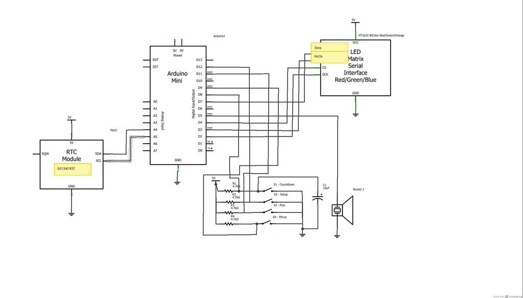
The device is designed to promote respectful time management during meetings, particularly useful in ship-room or SCRUM meetings. The following is a list of components required, including links for purchasing specific parts. It is advisable to check eBay or...