
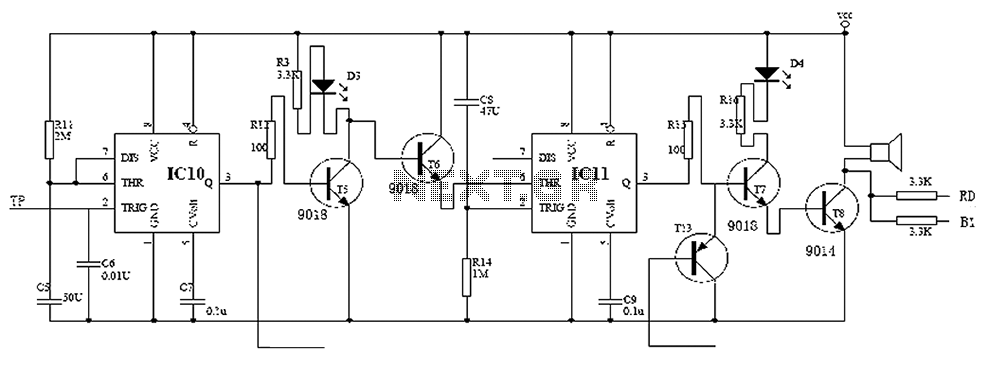
Electronic locks 555 monostable circuit diagram
This project considers two design options: one utilizing an AT89C2051 microcontroller as the core, and the other employing a digital logic control program using dual JK flip-flops (74LS112). Given the complexity of the microcontroller solution and the challenges associated with debugging, the latter option was chosen. The design incorporates nine user input keys, of which only four are valid password keys; the remaining keys serve as interference inputs. If an interference key is pressed, the keyboard input circuit is automatically cleared, requiring the user to re-enter the password. If the user exceeds a 40-second window to input the password, an alarm will sound after 80 seconds. If three consecutive incorrect attempts are made, the keyboard will lock for five minutes to prevent unauthorized operation.
The overall block diagram indicates that when someone approaches the door, a touch-sensitive terminal (TP) triggers the circuit due to the body's electrical capacitance, causing a state change in IC10. This results in a high output from pin 3 of IC10, turning on transistor T5, which is controlled by resistor R12. The collector of T5 is connected to a yellow LED (D3), indicating that the electronic lock is in standby mode. Transistor T6 is turned off, and capacitor C4 begins charging through resistor R14, allowing a 40-second window for the user to enter the password. If the password is not entered within this time frame, the circuit will trigger an alarm.
The alarm system is activated when an incorrect password is entered or if the 40-second limit is exceeded. The voltage at pin 2 of IC11 decreases as capacitor C4 charges. When this voltage drops to one-third of Vcc, pin 3 of IC11 goes high, activating transistor T7, which is limited by resistor R15 to prevent overcurrent. This turns on the red LED (D4) to indicate an alarm state and activates the buzzer via transistor T8, deterring potential intruders.
To stop the alarm, if the alarm time reaches 80 seconds, the discharge pins (6 and 7) of IC10 discharge capacitor C5, causing pin 3 of IC10 to go low. This action turns off T5, activates T6 to maintain a steady state, and sets pin 3 of IC11 low, which in turn deactivates transistors T7 and T8, silencing the buzzer. Alternatively, entering the correct password will trigger the unlocking circuit at the collector output of T10, clearing the alarm signal to transistor T12 (PNP), which turns on and forces T7 to a low state, disarming the alarm. Child lock voltage comparator 555 monostable circuit, a counter, JK flip-flop, UPS power supply design digital logic circuit, electronic door control, and a variety of addition al circuitry to ensure the safety circuit can work, a high safety factor. Circuit for modifying the password only 16, but because others do not know-digit password, but also request within the specified time to unlock a certain order, so little chance of unlocking others. Here people feel safer, more convenient and more comfortable new electronic lock design 555 monostable Circuit.
With the improvement of peoples living standards, how to achieve family security problem becomes particularly prominent, the traditional mechanical locks because of its simple structure, prizing common occurrence, electronic lock because of its high security, flexibility of use good high safety factor, the majority of users of all ages. When designing this project contemplates two options: one is the single-chip control program for AT89C2051 as the core; the other is for digital logic control program 74LS112 dual JK flip-flops.
Taking into account the principle of single-chip solutions complex and debugging more complicated, this article uses the latter scheme. Design ideas A total of 9 user input keys, of which only four are valid password key, the other keys are interference, when the key is pressed interference, keyboard input circuit is automatically cleared, invalid password previously entered, you need to re-enter; if time users to enter passwords more than 40 seconds (under normal circumstances, users will not exceed 40 seconds, and if users find it inconvenient, you can also modify) the circuit will alarm 80 seconds if the alarm circuit three times in a row, the circuit will lock the keyboard for 5 minutes, to prevent others the illegal operation.
The overall block diagram When someone approached the door, touch the end TP (TP end fixed on the keyboard, and its very high sensitivity to ensure reliable trigger circuit), due to the bodys own electrical tape to make IC10 2 feet appear low, so that the IC10 state overturns, its 3 feet high output, T5 is turned on (by R12 control T1 base current), its collector connected to the yellow light emitting diode D3, represents the electronic lock is now on standby, T6 off, C4 start by R14 (charging time is 40 seconds, this time for the user to enter time password that the user enter the password was not more than 40 seconds, otherwise the circuit began to alarm, since users often enter a password, and you know the password, the general password the time is not more than 40 seconds), IC2 start entry delay of 40 seconds status. Start alarm: when the user enters an incorrect password or a password longer than 40 seconds, and 2 feet of potential IC11 decreases as the charging of C4, when the potential drops to 1/3Vcc (ie the end of the time delay of 40 seconds), 3 pin goes high (when delay is low), by making R15 (R15 is to limit the effect of the conduction current T7 prevent overcurrent burned transistor) T7 is turned on and its collector connected to the red-light emission above diode D4 lights to indicate the current state of alarm, T8 also will be turned on, the buzzer sounding, so cowardly thief of life, to achieve the alarm.
Stop Alarm: When you reach 80 seconds alarm time, IC10 6,7 feet to the discharge end of the capacitor C5, IC10 3 feet into the low level, T5 deadline, T6 is turned on, forcing the circuit is in steady state mandatory, IC11 3 feet output low, T7, T8 is turned off to stop the buzzer alarm; or enter the correct password, there are unlocking circuit T10 collector output to clear the alarm signal to the T12 (PNP), T12 turned, forcing the T7-based extreme low, disarm the alarm signal.
Related Circuits
This is a low-cost protection circuit designed to safeguard electrically operated home appliances, such as TVs, DVD players, refrigerators, and other devices, during sudden power outages and the subsequent restoration of mains supply. Appliances like refrigerators and air conditioners...

This voltage booster circuit for driving one or more white LEDs utilizes a 555 timer as its main component. The timer, designated as IC1, operates as a resettable astable multivibrator with R1, R2, and C2 serving as the timing...
A simple water level indicator project with a circuit diagram for home and industry. This water tank level sensor can be utilized for any liquid level indicator projects. The water level indicator circuit is designed to monitor and display the...
This PWM controller circuit is suitable for managing small motors with a maximum current consumption of 2A. For higher currents, additional cooling is required. The PWM (Pulse Width Modulation) controller circuit is designed to efficiently control the speed of small...
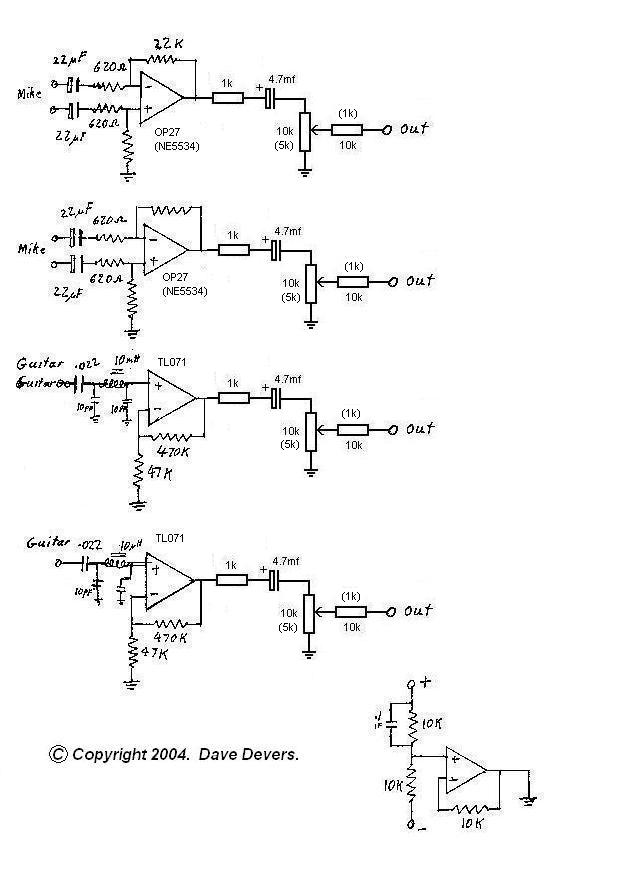
The mixer is extremely useful for direct input (DI) of guitars and basses into soundcards or other mixers, allowing for the utilization of channels on mixers that lack microphone inputs. It is particularly beneficial for one or two guitarists...
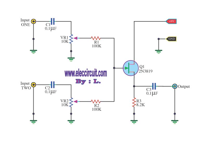
This circuit is a simple mixer circuit that can mix two signal channels into one output channel. It utilizes a codec circuit to convert stereo audio to mono audio. The main component in this circuit is a FET, specifically...