
Electronic Night Light
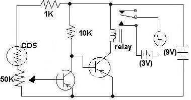
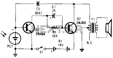
The described circuit utilizes two transistors configured as a direct-coupled switch, allowing for effective control of current flow based on light levels detected by a CDS photocell (ORP12). In this configuration, the first transistor is biased by a potential divider formed by the photocell, a 50kΩ variable resistor, and a 1kΩ resistor. Under normal lighting conditions, the resistance of the photocell is low, which ensures that the base of the first transistor receives sufficient voltage to turn it on, leading to a low collector voltage.
The choice of transistors such as the 2SC711, 2N3904, or BC109C is appropriate as they are general-purpose NPN transistors capable of handling the circuit's requirements. The direct coupling between the two transistors allows for a straightforward amplification or switching action, where the output of the first transistor can drive the second transistor directly.
The configuration of the potential divider is critical, as it sets the threshold at which the first transistor turns on or off, depending on the ambient light conditions detected by the photocell. As the light intensity increases, the resistance of the photocell decreases, allowing more current to flow through the divider, thus increasing the base voltage of the first transistor. This action results in the first transistor being fully on, which in turn keeps its collector voltage low, effectively turning on the second transistor (if connected) or controlling a load.
In summary, this circuit exemplifies a basic yet effective application of transistors and photoresistive elements for light-sensitive switching applications, suitable for various educational and practical implementations.This circuit was submitted by Adam from Canada who is still at school. I have provided the text. The two transistors are used as a direct coupled switch, Adam used 2SC711 but any general purpose transistor will do e.g. 2N3904, BC109C. The CDS photocell, type ORP12 is normally illuminated, therefore its resistance is low. The 50k control, the 1k resistor and the photocell form a potential divider which biases the first transistor. This transistor is on, its collector being held low, 🔗 External reference
Related Circuits
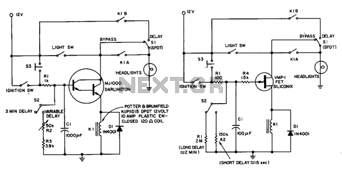
This circuit maintains the headlights of an automobile in an on state temporarily. It also ensures that the lights turn off automatically, even if the user forgets to switch them off manually. The shut-off delay is activated only when...
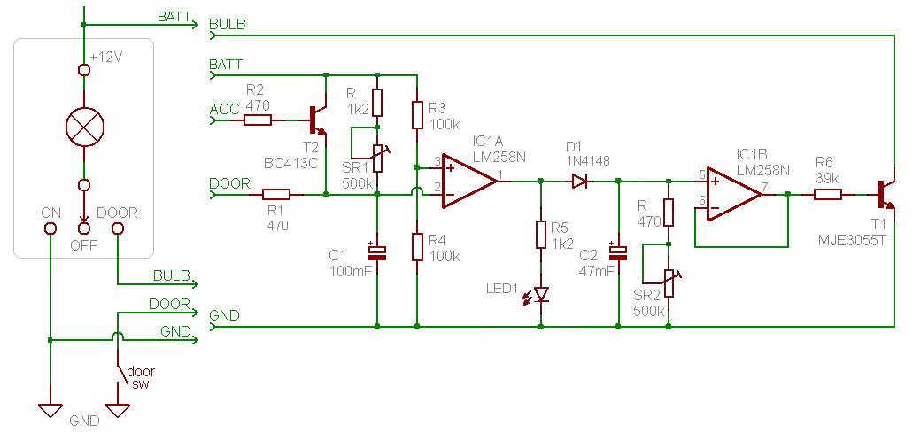
Introduction and disclaimer for individuals interested in a fading dome light (also referred to as courtesy light or theatre lighting) without incurring high costs. A fading dome light circuit is designed to create a gradual illumination effect, enhancing the aesthetic...
This circuit is a Low-Light Level Drop Detector. It utilizes a self-biasing configuration to detect small changes in light levels. The Low-Light Level Drop Detector circuit is designed to sense minute variations in ambient light conditions, making it suitable for...

Here is a simple thermostat circuit that can be used to control a relay and supply power to a small space heater through the relay contacts. The relay contacts should be rated above the current requirements for the heater....
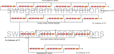
The following article outlines a sophisticated LED sequencing and diverging ring light that can serve as a tail brake light in vehicles. This circuit concept was proposed by a dedicated reader, Mr. Bobby. The design aims to create a...
This electronic music maker utilizes an astable oscillator circuit that is regulated by a photocell. The intensity of light falling on the photocell influences the tone. By enclosing the circuit within a box, it is possible to manipulate the...
Warning: include(partials/cookie-banner.php): Failed to open stream: Permission denied in /var/www/html/nextgr/view-circuit.php on line 713
Warning: include(): Failed opening 'partials/cookie-banner.php' for inclusion (include_path='.:/usr/share/php') in /var/www/html/nextgr/view-circuit.php on line 713