
Electronic Music Maker
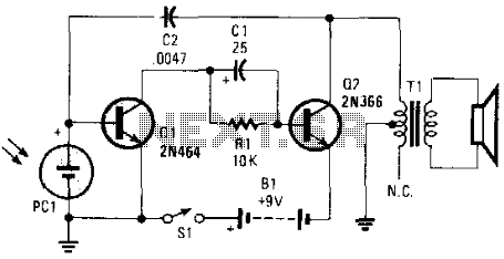
The electronic music maker operates on the principle of an astable multivibrator configuration, which generates a continuous square wave output. The frequency of this output is determined by the resistive and capacitive components connected to the circuit, as well as the resistance of the photocell, which varies with light intensity.
In this design, the photocell (light-dependent resistor, LDR) serves as a variable resistor that changes its resistance based on the amount of ambient light it receives. When light falls on the photocell, its resistance decreases, allowing more current to flow through the circuit. This change in current alters the timing components of the astable oscillator, effectively modifying the frequency of the output tone.
The schematic typically includes a power supply, which may be a battery or a DC power source, connected to the astable oscillator circuit. The circuit consists of two resistors, a capacitor, and the photocell. The output from the oscillator can be connected to a speaker or a piezo buzzer to produce sound.
Enclosing the circuit in a box allows for portability and ease of use, while also providing a way to shield the components from external light sources and interference. The design can be enhanced by incorporating additional features such as a potentiometer for manual control of the frequency, or an LED indicator that responds to the output tone.
This electronic music maker is not only an engaging project for hobbyists but also serves as an educational tool to demonstrate the principles of light sensing and sound generation through electronic circuits. This electronic music maker uses an astable oscillator circuit that is controlled by a photocell. The light falling on the photo cell controls the tone. By mounting the circuit in a box, you can control light-reading PCI with your hand. 🔗 External reference
Related Circuits

FGDF-3 is a three-phase low-temperature iron plating power commutation control switch and electronic circuit. The KGDF-3 serves as a low-temperature iron plating power supply device, incorporating the characteristics of a single-phase low-temperature iron plating power supply. This design facilitates...
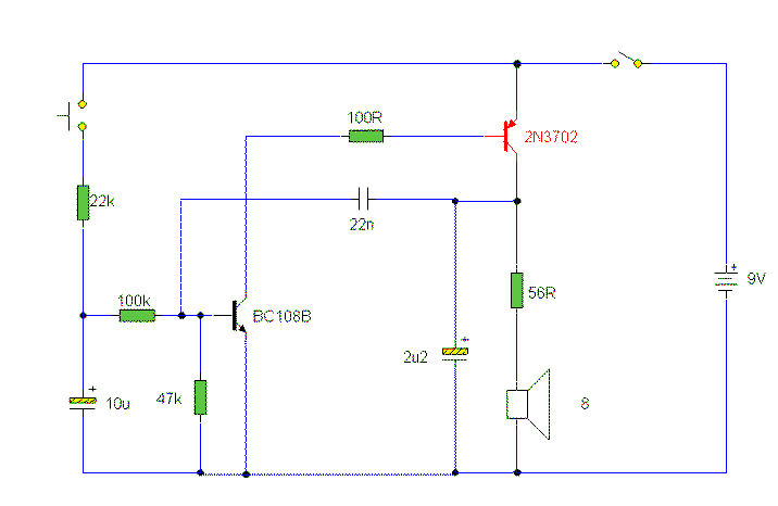
The sound produced mimics the rise and fall of an American police siren. When first powered on, the 10µF capacitor is discharged, and both transistors remain off. Upon pressing the push button switch, the 10µF capacitor begins to charge...
This power supply utilizes a single 7812 IC voltage regulator along with multiple external pass transistors, enabling it to deliver output load currents of up to 30 amps. The circuit design incorporates a 7812 linear voltage regulator, which is...
This review highlights a dual-test scenario involving the FVP preamp, with initial contacts made with Vacuum State and insights provided by Geoff during a trip to Brittany. The FVP was sent to France for evaluation. Geoff tested the FVP5A...
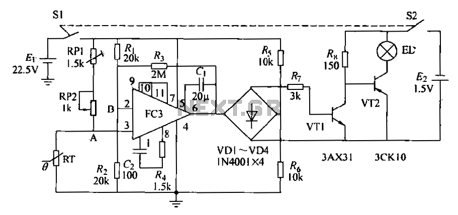
The circuit diagram illustrates an electronic thermometer. RT represents the thermistor, while A denotes an integrated operational amplifier. The diodes VD1 to VD4 provide a unidirectional output signal. The transistors VT1 and VT2 form a switching circuit. When the...
Doppler effect sensor N1 (RD627), operational amplifier N2 (LM358), and a special integrated circuit for imitating dog barking (N3, KD5608) are utilized along with other components. When there is no activity detected in the monitoring area by N1, the...