
Electronic pests killing lamp circuit diagram 4
The electronic pest-killing lamp circuit is designed to effectively eliminate pests using high-voltage electrical discharges. The oscillator generates a specific frequency that is essential for the operation of the entire system. It utilizes a time-base integrated circuit (IC) to produce a square wave signal, which is then shaped by the surrounding resistors (R5 to R7) and capacitors (C7 and C8) to achieve the desired voltage levels and timing characteristics.
The diodes (VD10 and VD11) play a crucial role in protecting the circuit from voltage spikes and ensuring that the oscillation remains stable. They help in directing the current flow appropriately, preventing reverse polarity that could damage the components.
The high voltage generator is responsible for stepping up the voltage to a level sufficient to create an effective electric field for pest elimination. This component typically consists of a transformer or a series of capacitors and inductors that work together to increase the voltage from the power supply to the required level.
The LED indicator circuit serves a dual purpose: it provides visual feedback to the user regarding the operational status of the circuit and can also indicate when the device is energized. This feature is essential for safety and usability, ensuring that users can easily determine whether the device is functioning properly.
The power supply circuit is designed to convert the incoming AC voltage to a suitable DC voltage level that powers the entire circuit. It may include components such as rectifiers, filters, and voltage regulators to ensure a stable and reliable power source.
Overall, the electronic pest-killing lamp circuit is a sophisticated assembly of components that work together to create a safe and effective pest control solution, leveraging electrical principles to achieve its intended purpose.The electronic pests killing lamp circuit consists of the oscillator, control circuit, high voltage generator, LED indicating circuit and power supply circuit, and the circuit is shown as the chart. The oscillator circuit is composed of the time-base integrated circuit IC, resistors R5 ~ R7, diodes VD10, VD11 and capacitors C7, C8.
Power supply circuit is co.. 🔗 External reference
Related Circuits
A minimum number of parts yields a compact switching converter that can provide sufficient voltage to drive white LEDs. The resulting lamp is much more efficient, in terms of lumen hours per pound of battery, than incandescent bulbs, and...
One of the critical components is a PWM speed controller, allowing for fine speed adjustments instead of just an "on" mode that runs at full power. This is important for safety. A basic stamp microcontroller was purchased, which includes...
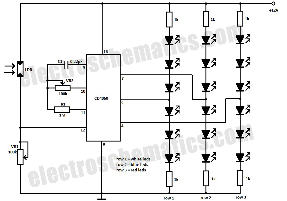
This simple Christmas LED lights decoration circuit allows for the creation of an 18 LED flasher to adorn a Christmas tree. The circuit incorporates white, blue, and red LEDs that flash in a festive pattern. The circuit is designed to...
Although it may lack the aesthetic appeal of traditional mercury barometers, which feature long glass tubes mounted on intricately carved and polished wood, the Torricelli barometer being discussed serves as a functional equivalent and electronic replica of the classic...
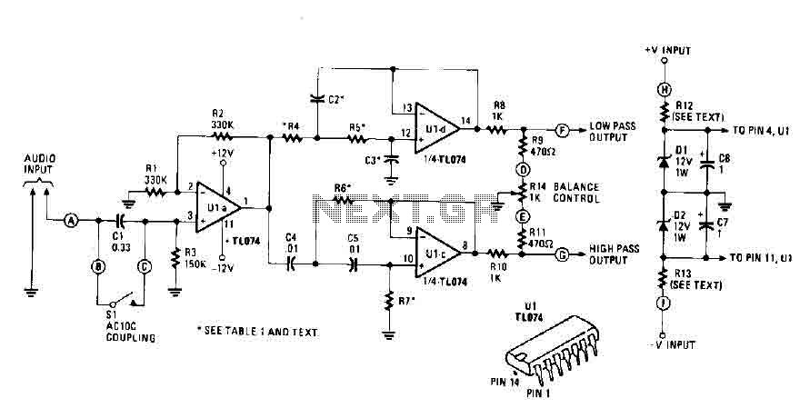
An audio source, such as a mixer, preamp, EQ, or recorder, is connected to the input of the Electronic Crossover Circuit. The signal can be either AC or coupled, depending on the setting of switch 51, which controls the...

The Mini AV Test Box circuit is designed with simplicity and efficiency in mind. It consists of three main sections, which are clearly delineated in the schematic. The primary components utilized in this circuit include the 7805 voltage regulator,...
Warning: include(partials/cookie-banner.php): Failed to open stream: Permission denied in /var/www/html/nextgr/view-circuit.php on line 713
Warning: include(): Failed opening 'partials/cookie-banner.php' for inclusion (include_path='.:/usr/share/php') in /var/www/html/nextgr/view-circuit.php on line 713